2
TECHNICAL SPECIFICATION
6
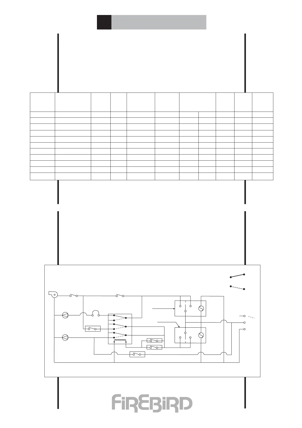
2-C Burner Settings Firebird Boiler Range Kerosene
Using RDB Range Of Burners (K).
2-D Wiring Diagram Combi Range
The above performance figures are based on ideal laboratory test conditions.
Air shutter settings above may need to be revised to take into consideration
difference in resistances between conventional and balanced flue installations.
Use flue gas analyser to achieve optimum results.
Variations in nozzle throughput, flue type & draught, oil viscosity etc. may
give results differing from these laboratory performance figures.
☛
☛
Range Burner Head Fuel Nozzle P.P. Air CO2 Fg. Smoke
Type Shutter Head No.
50,000 Riello RDB 1. T1 K .5 80’H 7 Bar 2.4 - 11.5 190 0-1
60,000 Riello RDB 1. T1 K .5 80’H 10 Bar 3.9 - 11.5 200 0-1
70,000 Riello RDB 1. T3 K .6 80’H 8 Bar 4.25 - 11.5 210 0-1
70,000 Riello RDB 1. T3 K .6 80’H 8 Bar 4.25 - 11.5 190 0-1
80,000 Riello RDB 1. T3 K .6 80’H 9.5 Bar 4.8 - 11.5 195 0-1
90,000 Riello RDB 1. T3 K .75 80’S 8 Bar 6 - 11.5 210 0-1
90,000 Riello RDB 2. T3 K .75 80’S 8 Bar 6 - 11.5 190 0-1
110,000 Riello RDB 2. T3 K 1.00 80’S 7 Bar 2.6 - 11.5 190 0-1
120,000 Riello RDB 2. T3 K 1.00 80’S 9 Bar 3.5 - 11.5 190 0-1
C.H. Pump
C.H. Timed Switch
Over Heat Stat.