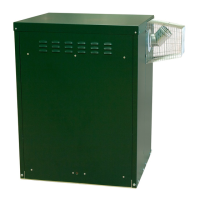
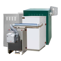
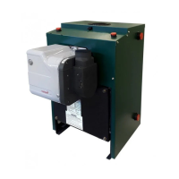
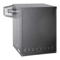
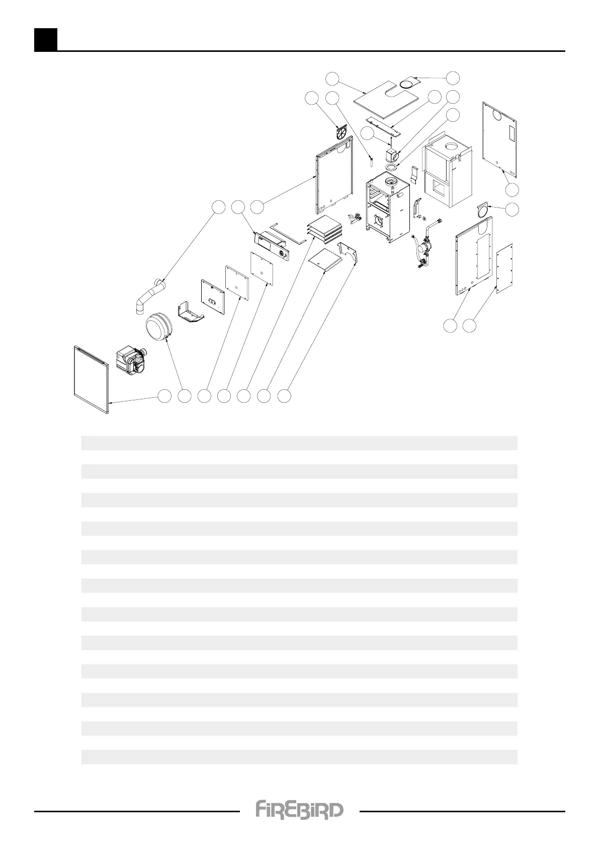
4 4.3 SYSTEM BOILER - TECHNICAL DETAILS
16
21
5 4
2
1
3
12 13
20
17
1110 14
17 7
6
8
9
15
18
19
For burner parts refer to burner manual
No. Qty Description
Sales Code
1 1 Deflector baffle 210049
2 1 Base baffle 210050
3 3 Smoke baffle 210060
4 1 Door gasket 113016
5 1 Ceraboard door 112368
6 1 Gasket seal 110555
7 1 Stat pocket ACC003PKT
8 1 Flue elbow adaptor 210249
9 1 Bolt M8X150 110437
10 1 Air hose ACC000SSH
11 1 Control panel 314734
12 1 Casing left side 214744
13 1 Casing side cover 214748
14 1 Casing right side 214745
15 1 Casing top support 214749
16 1 Casing front 214746
17 2 Side flue blank 114729 + 114730 + 114731
18 1 Casing top 214750
19 1 Top flue blank 114728 + 114729 + 114730
20 1 Casing back 214747
21 1 Expansion vessel 12 litre ACC012PVL
22 1 Pressure vessel ACC012PVL
19
SYSTEM 120 35kW BOILER