3 3.2 STANDARDS & REGULATIONS - FLUE SYSTEMS
9
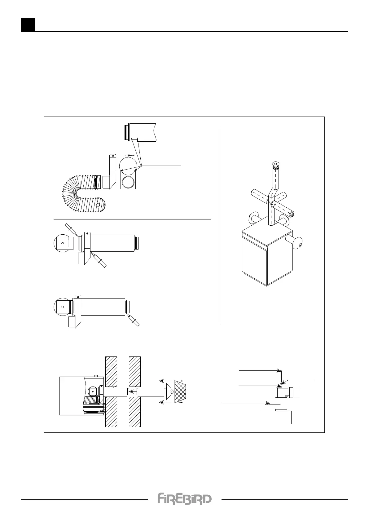
Balanced Flue System
IMPORTANT: THE INSTALLER MUST EXAMINE THIS ILLUSTRATION
CAREFULLY BEFORE PROCEEDING WITH INSTALLATION.
• The Firebird low level concentric ue kit has been specically designed for Firebird’s indoor boilers.
The use of third party low level ue kits is not recommended and may affect its warranty.
Locating points for xing
air box to ue pipe.
Push the ue adaptor in
to ue collar.
Push the ue pipe through
the 125mm hole in the wall.
Secure the ue
adaptor to the
boiler.
Apply high temperature sealant
to the O ring on the inner ue
pipe to ensure a positive seal.
IMPORTANT:
A 50mm - (2inch) gap
must be left between the
cone cowl and the wall.
Ensure Combustion air pipe
protrudes beyond the outer
surface of the wall.
GAS GAS
GAS
GAS
GAS
GAS
M8 x 130mm bolt
M8 ber washer
Ceramic gasket seal
M8 washer
ENSURE UNRESTRICTED AIR-SUPPLY TO BOILER ROOM.
No further adjustments are required for adequate combustion-air supply.
Check burner operation when installation is completed.
Use burner Combustion Analyser to ensure correct performance.
Consult separate burner manual supplied with boiler.
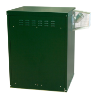
High Level Balanced Flue:
• Right hand outlet.
• Left hand outlet.
• Rear outlet and top outlet.
Apply high temperature
sealant to the inside of
ue collar.
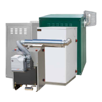
Balanced Flue:
• Right hand outlet.
• Left hand outlet.
• Rear outlet.
GAS
GAS
GAS
GAS
GAS
GAS
GAS
GASGAS