6
Part Number 18002, G, 09/24/2019
Installation
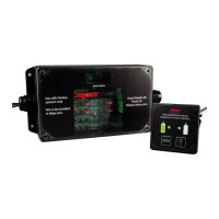
Installing the Engine Shutdown Control Module
The Engine Shutdown Control Module should be located near the helm where convenient access
to the ignition wiring is available. Use appropriate length #8 screws and secure using all 4
mounting holes.
CAUTION:
NEVER INSTALL THE ENGINE SHUTDOWN CONTROL MODULE IN A BILGE AREA OR ENGINE ROOM.
Installing the Helm Display Unit
The Helm Display should be located at the instrument panel, so that the visible and audible
indicators may be easily observed.
Drill a 2-1/8” hole to accommodate the DU-SBH-20 and DU-SBH-21.
Insert Display Unit into hole and secure with the provided threaded mounting nut.
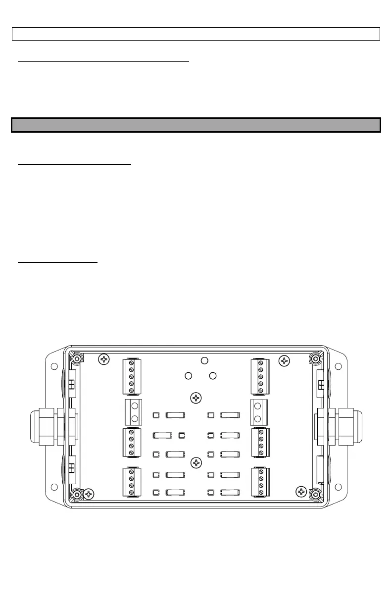
Electrical Connections
Wiring must be made using #16 stranded copper wire conforming to ABYC Standards for Marine
use, as a minimum (SAE J378B & J1128). Connections to the terminals must be made with bare
wire. Route wires through the loosened strain reliefs on the side of the box, closest to the
terminal being used. Additional strain reliefs may be added, Fireboy-Xintex P/N: 63020 (Heyco
P/N: M3216), clearance hole is .813in (20.6mm). The Terminal strips disconnect from the Engine
Shutdown Control Module for easier installation.
 Loading...