2/12 Fixing instructions Doc. version 1.0
Panel Accessories FIRECLASS Fire detection system
Installing the Ethernet
Switch (POS800/PCS800) on
a FireClass Panel
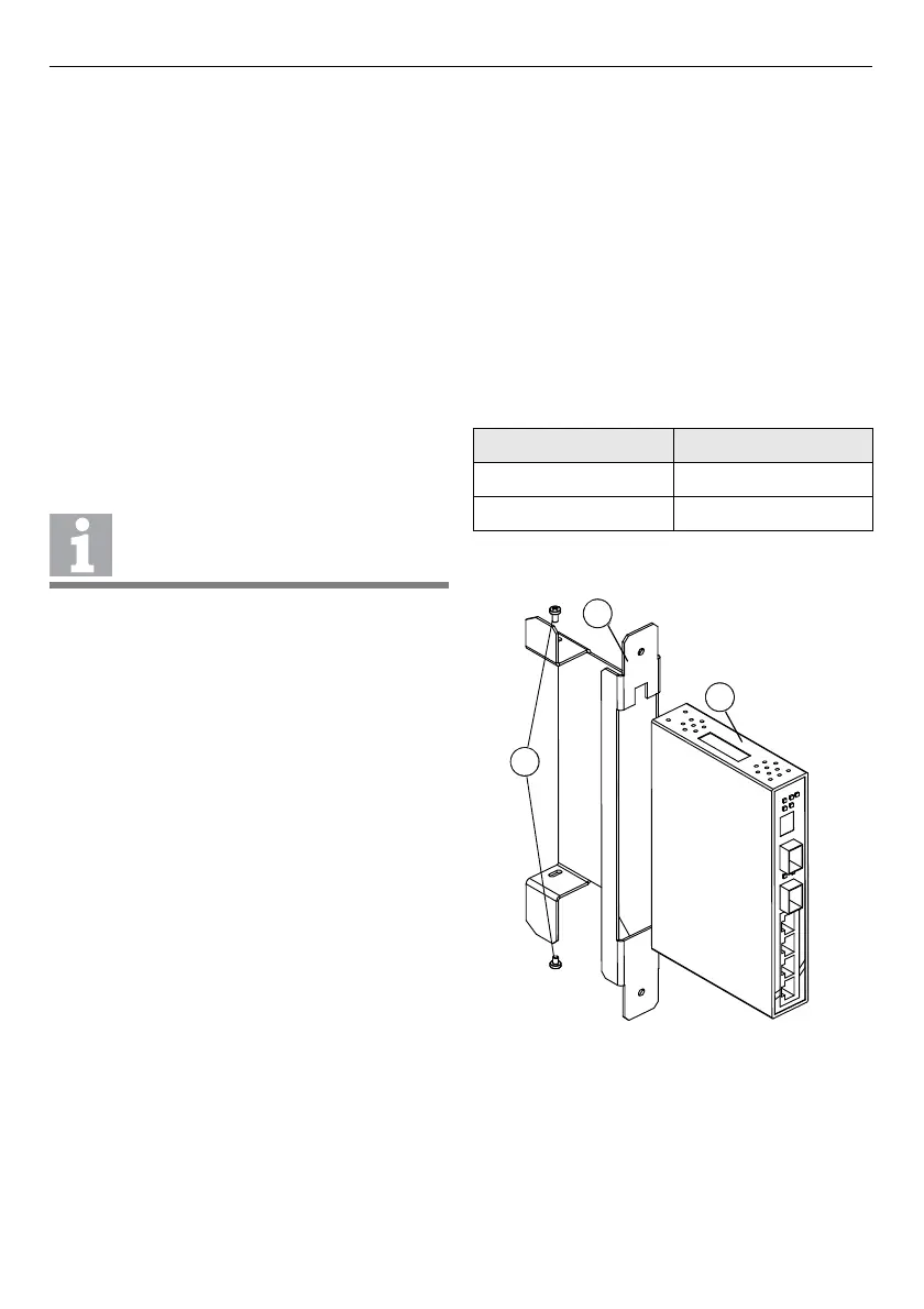
1 Slide the Ethernet switch (refer to item 1 in
Fig. 1) into the slot cage holder (item 2).
2 Align the back of the Ethernet switch with the
back of the slot cage holder and secure it with
the screws supplied (item 3).
3 Prepare the power supply cables and feed
them through the top of the slot cage holes
(refer to item 4 in Fig. 2). Connect the wires
into the terminal block on the Ethernet
switch. Observe the correct polarity. If you
require redundant power supply wiring, fol-
low the same procedure.
4 Fit the other end of the cable to the FC-FI
board (XT6 or XT7 connectors) using the con-
nector supplied with the FC-FI. Refer to Table
3. Use both XT6 and XT7 connectors on the
FC-FI board for a redundant power supply.
5 The POS800 Ethernet switch also provides a
volt-free relay contact to which you can con-
nect the FC-FI isolated inputs (ISOLIN 1, ISO-
LIN 2) for fault monitoring. If required, con-
nect a bypass wire from V1+ (pin 5) on the
Ethernet switch connector to pin 4 on the
same connector. Additionally, connect the
wire from pin 3 on the Ethernet switch to
ISOL IN+ on the FC-FI board and from V1- on
the Ethernet switch to ISOL IN– on the FC-FI.
Refer to Fig. 3. Use a minimum 16/0.2 wire
(not supplied).
Note: Using a volt-free relay contact on the
Ethernet switch allows the panel to see faults
which would otherwise go undetected (for
example, a power port failure or an Ethernet
port downlink). You can select situations in
which the relay will actuate in configuration
on an individual basis (see the section, “Con-
figuring the POS800-S and POS800-M Ether-
net switches”). Each Ethernet switch reports
only faults related to its own ports.
6 Plug the power supply connector into the
Ethernet switch.
7 Fit the fibre-optic modules into the Ethernet
switch and connect the optical cables
(POS800 only).
8 Slide the slot cage holder (refer to item 2 in
Fig. 2) into the slot cage in the panel.
9 If the switch is a POS800, attach the fibre-
optic holder (item 5) into the slot cage and
secure it with screws (item 3).
10 Connect the metallic cables from the GUI and
the FC-FI board to the Ethernet port on the
switch.
A redundant cable is not provided. If
required, use a minimum 16/0.2 wire.
XT6, XT7 Ethernet Switch
+24V V1+
-V1-
Table 3: FC-FI connections
Fig. 1: Mounting the Ethernet switch to the slot cage
holder
1 – Ethernet switch
2 – Slot cage holder
3 – Screws