1
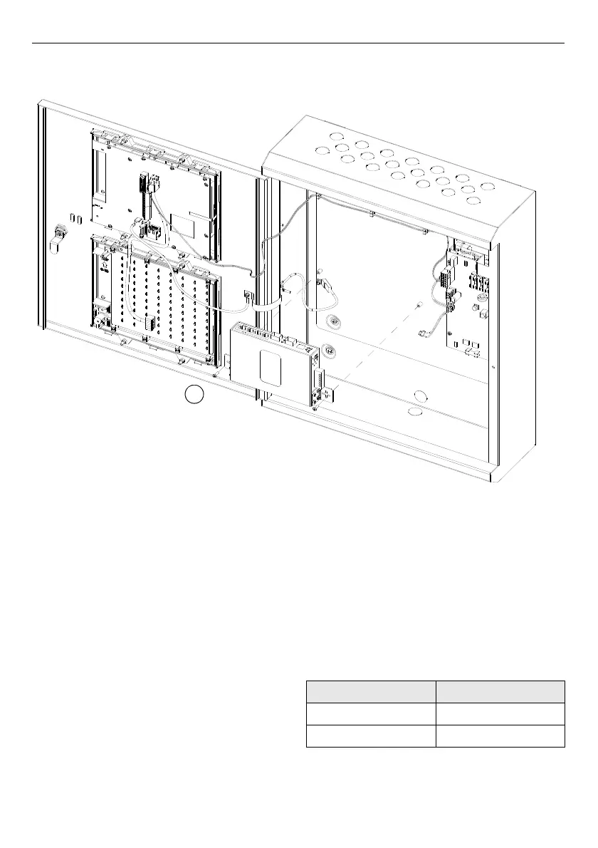
Fig. 4: Installing the Ethernet switch on a FC8AS AC repeater
1 – Earth cable screw (optional)
4/12 Fixing instructions Doc. version 1.0
Panel Accessories FIRECLASS Fire detection system
Installing the Ethernet Switch on a FC8AS AC
Repeater
To mount the Ethernet switch on an FC8AS
repeater, complete these steps:
1 Ensure that the panel is isolated from the
mains and it is not running on batteries.
2 Mount the fixing elements (refer to item 2 in
Fig. 4) with screws (supplied) on the Ethernet
switch housing.
3 Connect the DC power supply to the Ethernet
switch connector (refer to item 4 in Fig. 4),
observing the correct polarity. If you require a
redundant power supply, connect a minimum
16/0.2 wire (not supplied).
4 Connect the other end of the DC supply cable
to the PMM800 board. Refer to Table 4.
5 If you require a redundant supply, use the
other pins on the same terminals on the
PMM800 board and connect to V2+ and V2-
on the Ethernet switch.
6 Fit the fibre-optic modules on to the Ethernet
switch and connect the optical cables.
7 Connect the metallic cable from the GUI to
the Ethernet port on the switch.
PMM800 Ethernet switch
24V (TB6) V1+
0V (TB4) V1-
Table 4: Power supply wiring connection