FIRECLASS Fire detection system Panel Accessories
Fixing instructions Doc. version 1.0 5/12
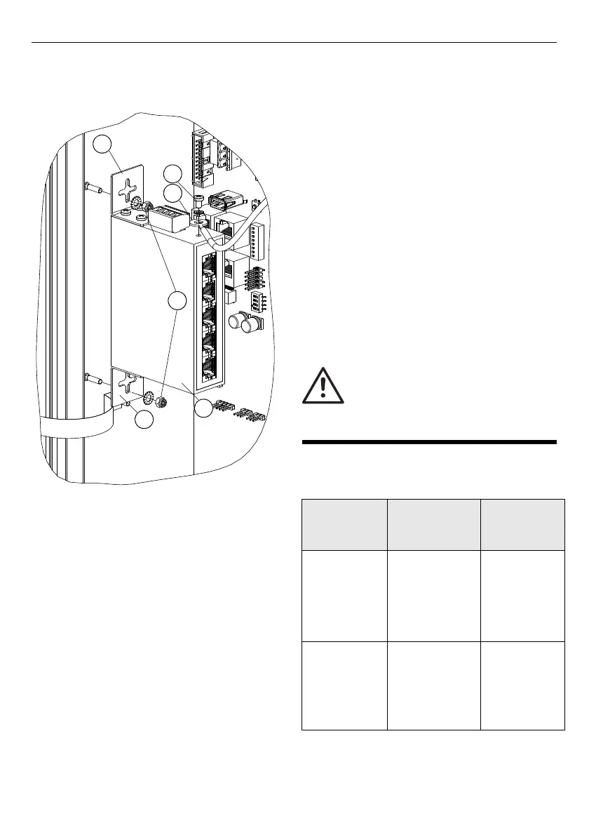
Installing the PCS800 on a
FireClass FC702S Panel
To install the PCS800 Ethernet switch on a
FC702S panel, complete these steps:
1 Mount the fixing elements (refer to item 3 in
Fig. 5) with the screws provided on to the
Ethernet switch housing.
2 Fix the Ethernet switch on to the chassis
studs with nuts and washers (item 2).
3 Fix the Earthing cable (item 5) supplied with
the switch accessories to the top of the
Ethernet switch. Secure the cable with a fix-
ing screw (item 4) and connect the other end
to the housing earthing bar.
4 Connect the DC power supply cable to the
FC-FI connector. Refer to Table 4. Connect to
XT6 or XT7, (or both if you require a redundant
supply) and to the PCS800 connector.
5 If you require a redundant supply, use the
same terminals on the PMM800 board and
connect to V2+ and V2-.
6 Plug the DC power supply into the Ethernet
switch.
7 Connect the Ethernet cabling.
Configuring the POS800-S
and POS800-M Ethernet
switches
To configure a POS800-S or a POS800-M Ether-
net switch, complete these steps:
1 Configure the DIP switch on the front of the
Ethernet switch. Refer to Table 5.
Fig. 5: Installation of the PCS800 to the FireClass
FC702S panel
1 – Ethernet switch
2 – Washers and nuts
3 – Fixing elements
4 – Earth cable fixing screw
5 – Earthing cable
CAUTION
Before configuring an Ethernet switch,
ensure that you disconnect all devices
that are connected to it (apart from your
computer).
Redundant
optical
connection
Redundant
metallic
connection*
Single line
connection
Ethernet
switch no.1:
Position1 -
OFF. Position
2,3,4 - ON
Ethernet
switch no. 1:
Position 1,4 –
OFF. Position
2,3 – ON
All positions
OFF
Ethernet
switch no.
2,3,...:
Position 1,3 -
OFF. Position
2,4 - ON
Ethernet
Switch no.
2,3...:
Position 1,3,4 –
OFF. Position 2
– ON
-
Table 5: POS800-S/POS800-M configuration
* Supported on port 1 and 2 only