EasyManuals Logo

FireClass FC700 Series User Manual

FireClass FC700 Series
12 pages
To Next Page IconTo Next Page
To Previous Page IconTo Previous Page
Page #7 background imageLoading...
Page #7 background image
FIRECLASS Fire detection system Panel Accessories
Fixing instructions Doc. version 1.0 7/12
ON
1234
P1 P2 FAULT
RING R.M.
P.F.
R.E.
R.M.
R.S.
P1/P2
P5/P6
2
3
4
5
6
7
8
9
10
11
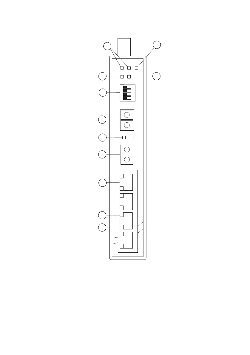
Fig. 6: POS800/PCS800 Ethernet switch
1 LED for PWR1, LED for PWR2
2 LED for fault relay
3 – LED for ring
4 LED for R.M. (ring master)
5 – DIP switch setting:
P.F.: Power fault warning (ON for enable, OFF for
disable)
R.E.: Ring topology (ON for enable, OFF for
disable)
R.M.: Ring Master (ON for enable, OFF for
disable)
R.S.: Ring Select (P1/P2L Port 1 and Port 2, P5/P6:
Port 5 and Port 6)
6 100 base fibre port on SFP (Port 6)
7 LED for SFP LINK/ACT
8 100 base fibre port on SFP (Port 5)
9 – 10/100Base-T(X) Ethernet ports
10 –LED for Ethernet ports ACT status
11 –LED for Ethernet ports LINK status
1
2
3
4
5
6
7
8
9
10
11

Questions and Answers:

Question and Answer IconNeed help?

Do you have a question about the FireClass FC700 Series and is the answer not in the manual?

FireClass FC700 Series Specifications

General IconGeneral
BrandFireClass
ModelFC700 Series
CategorySwitch
LanguageEnglish

Related product manuals