Do you have a question about the Firefly Galleria and is the answer not in the manual?
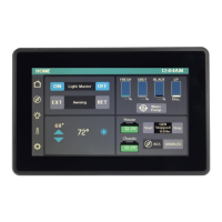
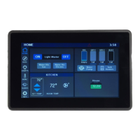
Controls all interior lights; remembers previous settings or turns all on.
Extend (EXT) or Retract (RET) the awning. Ignition must be off.
Use arrows to set the desired temperature for climate control.
Displays icons for Air Conditioning (snowflake) and fan speed (H/L).
Details how water and LP tank levels and propane are displayed based on percentage.
How to toggle the Water Pump On/Off via the interface.
Explains house and chassis voltage readings and their display indicators.
Instructions for starting and stopping the generator, and setting its operating hours.
How to enable/disable AGS, including safety warnings and setup steps.
Set automatic generator start triggers (Low Volts, HVAC) and define quiet periods.
Configure voltage thresholds for starting/stopping and set generator minimum/maximum run times.
Configure the number of attempts the system makes to start the generator if it fails.
Operate AC and fan settings using predefined High/Low fan speeds.
System automatically controls fan speed or allows manual percentage adjustment.
Navigate to the Vegatouch Mira connection screen.
Access the Network Diagnostics screen for troubleshooting.
Access manufacturer-specific settings and options.
Select between Fahrenheit and Celsius for temperature display.
Locate login details and download the Vegatouch Mira app.
Scan for the Mira Module's signal and authenticate with ID and PIN.
Instructions for enabling Bluetooth on iOS devices for Mira connection.
Grant location access for Android devices to connect with Mira.
Choose between Fahrenheit and Celsius for temperature display.
View system versions, module name, and coach details.
Option to disconnect the current device from the Mira module.
Force a download of configuration files from the cloud.
Display a list of all currently connected devices.
Instructions for enabling remote help via consultation with Tech Support.
Interpret battery graphics to determine switch panel connection status.
Steps to pair a wireless switch panel by pressing buttons.
View status of touchscreens, G8 panel, and Aircon, identifying faults.
Identify which individual G8 outputs are currently active.
Explains how G8 panels control circuits and indicate status with LEDs.
Guide on using a multi-meter to test output voltage on G8 circuits.
Details wiring for high current outputs (20A max) on the G8 panel.
Explains inputs for thermistors and ground connections.
Details wiring for low current outputs on the G8 panel.
Details inputs for generator status, voltage, and ignition.
| Brand | Firefly |
|---|---|
| Model | Galleria |
| Category | Automobile Accessories |
| Language | English |