6-Propane and Natural Gas Safety
IMPORTANT: READ AND FOLLOW ALL WARNINGS PROVIDED WITH THE PROPANE-GAS CYLINDER.
READ ALL SAFETY INSTRUCTIONS AND WARNINGS REGARDING THE USE OF PROPANE GAS FOUND
IN YOUR OWNER’S MANUAL. FOR NATURAL GAS READ ALL SAFETY INSTRUCTIONS AND WARNINGS
FOUND IN YOUR OWNER’S MANUAL.
7-Routine Maintenance
Your grill must be serviced and maintained properly to ensure optimal performance, appearance, and safety. The grill must be cleaned
as often as twice a month (depending on use) to prevent grease build-up and other food deposits. See owner’s manual for details.
REV 6 - 1804201255
L-C2-336
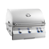
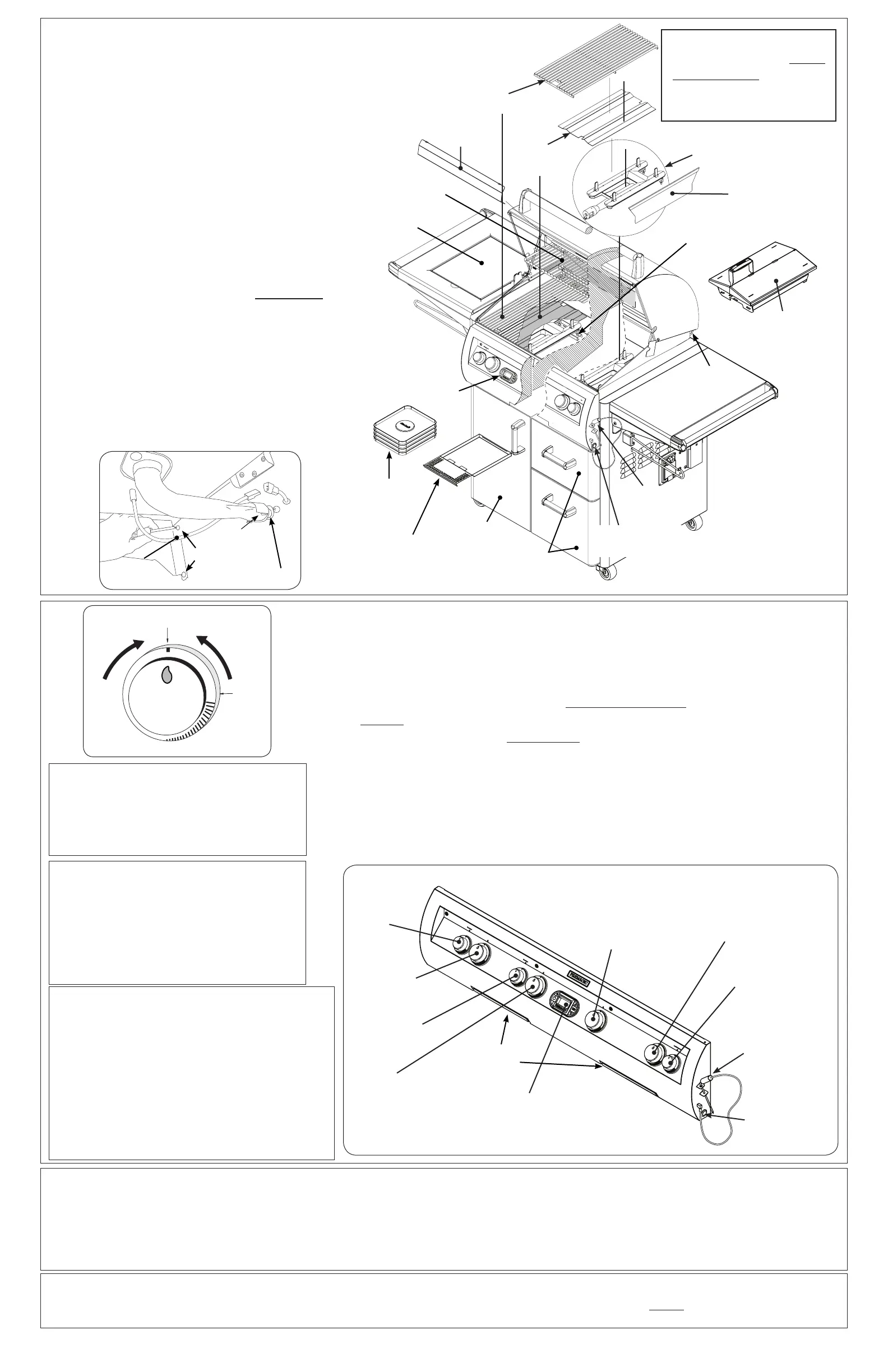
Fig. 4-1
Cooking grid
Flavor grid
(not with IR)
Backburner
cover
Warming
rack
Cotter
pin
Rotisserie
rod storage
ring
Sideburner
lid
Meat probe
(if equipped)
Drip tray
liners
Drip tray (with
lighting instructions)
Door
Drawers
E-burner
*
(comes pre-installed)
Charcoal/smoker
basket
Heat zone
separator
Digital
thermometer
(if equipped)
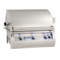
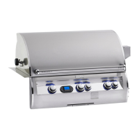
Fig. 5-2
Left main
burner
control knob
Right
main burner
control knob
Digital thermometer
(if equipped)
Center right main burner
control knob
Center left main
burner
control knob
Right backburner
control knob
(if equipped)
Left
backburner
control knob
(if equipped)
Pull-out drip
tray(s)
Meat probe
(if equipped)
5-Test
Note: This unit must be connected to 120VAC power for electronic lighting.
1. Open lid(s) or remove cover(s) from burner(s) to be lit.
2. Turn all gas control knob(s) to their OFF position(s).
3. Turn on the gas at its source and if equipped, press the master switch.
Note: DO NOT turn on more than one valve at a time for either electronic or manual lighting.
4. Depress the desired control knob for 5 seconds, then, while pressing turn it counterclockwise to the
HI LIGHT position. Once the burner lights, release the knob.
CAUTION: If a burner does not light within five (5) seconds of turning on the control
knob, depress the knob and turn it to the OFF position.
WAIT FIVE (5)
MINUTES before repeating step 4. If you smell gas, follow the instructions on the cover
of the grill owner’s manual. If the burners still do not light after several attempts, refer to
the grill owner’s manual for manual lighting.
5. Repeat step 4 for each additional burner to be lit.
Sideburner
control knob
WHEN OPERATING THIS GAS
APPLIANCE, ALL INSTRUCTIONS
AND WARNINGS MUST BE
OBSERVED. FAILURE TO DO SO MAY
RESULT IN A FIRE OR EXPLOSION
CAUSING PROPERTY DAMAGE,
BODILY INJURY, OR DEATH.
For your convenience and safety;
when the control knob is turned
to the ON position, the gas ow
indicator will change from blue to
red. (Red indicates gas ow.) See
Fig. 5-1.
Fig. 5-1 - Burner valve control knob
OFF
HI
LIGHT
LOW
T O
TURN OFF
T O TURN ON
Read setting
here
HIGH to
LIGHT
Read setting here
(OFF position shown)
To Turn OFF
To Turn ON
Use
HI (high)
to light
Press
knob in
to turn
Gas Flow
Indicator
(E1060i model with digital
thermometer shown)
Master / Light
switch
‡
MASTER SWITCH (digital thermometer models)
The master switch (Fig. 5-2) controls the power to
all lights, igniters, and the thermometer. It allows
the power to be turned on or off for safety and
convenience. The switch will need to be turned on
prior to each grill use, and turned off after each
use.
LIGHT SWITCH (analog models)
The light switch (Fig. 5-2) is push button operated,
and is located on the right side of the control
panel. It controls the power to all lights.
‡
Master / Light
switch
Parts Placement Checklist
Place the following items according to their position and
orientation in Fig. 4-1:
Flavor grids, cooking grids, heat zone separators, backburner
cover, warming rack, and meat probe.
Leave pre-installed E-burners in place to maintain proper
alignment.
Backburner Cover(s)
Hook the backburner cover(s) over the top of the backburner(s)
to protect the backburner(s) from grease, dust and dirt when
it is not in use. Remove cover(s) before use.
Warming Rack
The warming rack comes pre-installed. Remove zip ties
before use. Consult the owner’s manual to remove or replace.
Charcoal / Smoker Basket (if equipped)
The basket is for use directly above a main burner. Consult
the owner’s manual for complete installation and operation.
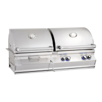
Shelf/Sideburner (if equipped)
Align the four (4) holes in the shelf with the four (4) holes in
the side of the cart while aligning and engaging the burner
venturi with the orifice (Fig. 4-2). Insert the four (4) screws
(provided) into the holes and tighten. Connect the spark wire
to igniter electrode (Fig. 4-2). Open sideburner lid, set cap
on burner, and set grid into shelf.
IMPORTANT: See your grill owner’s manual for complete
installation details.
4-Grill Setup
Screws
Air shutter
Orifice
Igniter wire
Fig. 4-2
Venturi
*
The burner ports and
carry-over slots must
be kept clean to ensure
proper ignition and
operation.
Replacement parts can
be ordered from your
local Fire Magic dealer.
Note: For infrared burner, double sideburner
and powerburner equipped grills; see
detailed instructions included in your
owner’s manual.

 Loading...