INSTALLATION PROCEDURE (continued)
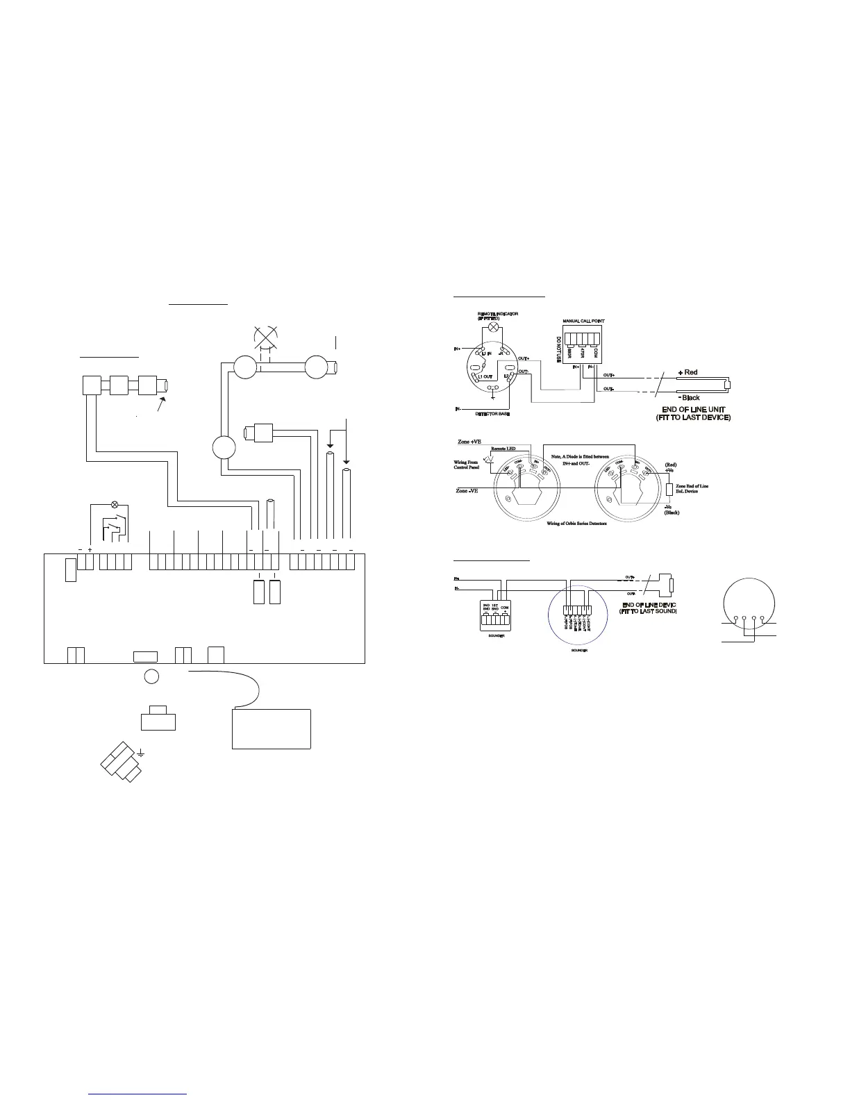
D) Connect the cables from the zones (detectors)
and alarms (sounders) to the pcb as shown in
diagrams, ensuring that there are
NO spurs from
the main circuit. Fit the end-of-line component
onto the last detector or call-point of each zone
circuit. The end-of-line resistor used on the alarm
circuit can be connected either way round. For
any unused circuits, leave the end-of-line
component / resistor in the terminal block
located on the pcb.
E) The panel has several optional inputs and
outputs.
• AUX 1 & 2 -Are volt free relay contacts which
change over when the alarm sounds –Used for
switching auxiliary equipment.
• AUX 24V - a 24v DC power supply used to power
auxiliary equipment.
• CLASS CHANGE - wire a switch between COM and
CC terminals to make the sounders operate.
• PULSE ALERT - wire a switch to terminals BA and
COM to make the sounders pulse.
• FAULT - Volt free changeover relay contacts that
duplicates the common fault indicator. Used to
drive a remote fault indicator.
TYPICAL PANEL WIRING
NO SPURS ALLOWED
E
ND OF LINE COMPONENT
ON LAST DETECTOR
Zone +Ve
RED
Zone -Ve
BLACK
EOL COMPONENT
O
N ANY UNUSED ZONE
TYPICAL ALARM WIRING
AL2 WIRED AS AL1
END OF LINE RESISTOR
ON LAST SOUNDER
AUX 2AUX 1
FLT 1
REMOTE INDICATOR
FLT 2
N/C
N/C
N/C
N/C
COM
COM
COM
COM
N/O
N/O
N/O
N/O
AL 2
AL1
F4
1A
(T)
1A
(T)
F3
ZN 1 ZN 2 ZN 3 ZN 4
+
++
-
+
+
+
+
AUX
24V
O/P
BA
CF
CC
COM
F5 250mA(T)
F6 6.3A(T)
TF
AC
BATT
MAINS
CABLE ENTRY
CABLE CLAMP
FUSE F6 = BATTERY SUPPLY (6.3A)
FUSE F5 = AUXILLIARY OUTPUT (250mA)
FUSE F4 = ALARM CIRCIUT 1 (1A)
FUSE F3 = ALARM CIRCUIT 2 (1A)
BATTERY
L
N
250Va.c 1A(T)
20*5mm FUSE
CONTROL PCB
EARTH
DD
D
SSS
C