INSTALLATION PROCEDURE
The following instructions must be followed, however
it is recommended that the installation is delayed
until all the building or maintenance work is
completed. Building work near the panel may result
in damage.
Remove the fire panel from the packaging, but retain
this for the future storage of panel parts during
installation.
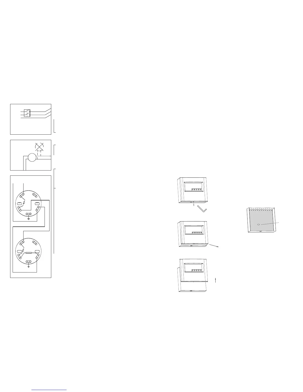
A) To remove the front – remove the screw located
under the bottom edge of the panel using Allen
key provided, pull the bottom edge out then lift
up. Store the panel front face down in the
packing box tacking care of the led light guides
on the back.
B) Box Mounting - Once the cable entry routes have
been decided, remove the appropriate knockouts
situated on the top and back of the box by
carefully knocking out from the inside outwards.
Note the entry point for the mains cable is
through a knockout which is located at the back
of the back box – see below. Ensure that the
back box is securely and flush fitted to the fabric
of the building. The box should be mounted at
such a height that the push buttons and LED’s
are at eye level. When mounting the box take
care not to damage the pcb in the box. Remove
any debris.
C) Feed the required cable into the box then make
off a reasonable working length, (identify each
of the cables).
Conduct all installation tests on
the cables with the detectors and other
electronic devices disconnected. Failure to
observe this could result in serious damage to
the detectors etc.
SYSTEM DESIGN GUIDE
When installing the system the designer should ensure:-
1. The installation complies with the relevant code of practise for
installations.
2. The mains supply is switched via a double pole isolator.
3. All detectors are sighted in accordance with British standard
recommendations.
4. That detector and alarm sounder circuits have NO SPURS.
5. It is recommended that the cabling used for detector and alarm
circuits is 1.5mm
2
Fire Protected, 2-core + screen complying with
BS7629, BS7846 and BSEN60702 (BS6207).
6. That detectors and callpoints used are compatible with the panel,
and that only devices recommended by the supplier are used.
7. The correct end of line component is used on the detection and
alarm circuits (including those not used), These components must be
fitted after the last detector, callpoint or sounder.
8. The total current consumption for each zone of detectors does not
exceed 4mA
9. The detector bases are connected as shown and must be fitted with a
diode for detector removal fault. Otherwise the removal of a detector
from a base will prevent subsequent detectors and call-points on the
zone from functioning.
10. The sounders must have a series blocking diode with suppression
components fitted that only allows current to flow through the
sounders when the control panel pcb is wired as shown.
11. Sounder current consumption should not exceed the panel
maximum. The maximum load for each set of contacts is 1A, however
the total sounder current should not exceed that shown in table for
panel specification.
12. That if a 24V auxiliary output is used for powering an auxiliary
circuit, the battery standby period is checked to ensure that the
maximum duration required for the installation can still be achieved.
 Loading...