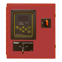
Do you have a question about the Firetrol Jockey XG FTA550 and is the answer not in the manual?
| Brand | Firetrol |
|---|---|
| Model | Jockey XG FTA550 |
| Category | Controller |
| Language | English |
Details the necessary tools, materials, and procedure for wall-mounting the controller enclosure securely.
Provides crucial precautions and step-by-step procedures for connecting electrical wiring to the controller.
Explains the required system pressure connection and the fitting used for the controller's sensing line.
Procedure to verify incoming line voltage matches the controller's data plate specifications.
Steps to 'bump' the motor and confirm correct rotation direction after initial connections.
Explains manual/automatic modes and how the XG Pump Controller manages motor start/stop based on pressure.
Provides essential information on password protection, user-defined functions, and setting indicators.
Details the specific password required for accessing and modifying user programmable functions.
Instructions for adjusting brightness, contrast, invert display, and keyboard inactivity timeout.
Details on setting passwords for Level 1 and Level 2 access, with notes on password management.
Settings for On Delay, Minimum Run time, and Restart delay for the jockey pump motor.
Configuration of pressure units, start and stop pressure settings for the pump.
Enables/disables the overpressure alarm feature and sets the pressure limit.
Procedure to set the zero calibration value for the pressure sensor using a jumper and gauge.
Adjusts the span setting to match the pressure gauge reading after zero calibration.
Resets pressure settings to factory defaults, disabling user calibration settings.
Sets the differential percentage between phases to trigger a phase imbalance alarm.
Enables/disables user defined alarms and configures associated audible/common alarm outputs.
Explains the event log's function as a record of the last 3000 events and how to browse them.
Details factory-set parameters for Serial Number, Model, Horsepower, and Voltage.
Provides raw input/output values for factory-level troubleshooting purposes.
Provides options for clearing data history, event logs, and resetting to factory defaults.
Resets the controller to 'out of the box' default settings, losing all configuration.
 Loading...