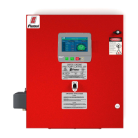
The Firetrol MarkIII+ Electric Fire Pump Controller is designed to manage and operate electric motor-driven fire pumps, ensuring the reliable activation and shutdown of the pump in fire suppression systems. This controller offers a range of starting and stopping methods, catering to various operational requirements and safety protocols.
Function Description
The primary function of the Firetrol MarkIII+ controller is to initiate and terminate the operation of an electric fire pump. It can be started manually via a local pushbutton or automatically when a pressure drop is detected in the sprinkler system by a pressure transducer. Stopping the pump can also be done manually using a local stop pushbutton or automatically after a field-programmable timer expires, provided all starting conditions have ceased.
The controller supports several starting methods:
- Automatic Start: The pump starts automatically when the pressure sensor detects a drop below a predefined cut-in threshold.
- Manual Start: The motor can be started by pressing the START pushbutton on the controller, irrespective of system pressure.
- Remote Manual Start: The motor can be started remotely by momentarily closing a contact from a manual pushbutton.
- Remote Automatic Start / Deluge Valve Start: The motor can be started remotely by momentarily opening a contact connected to an automatic device.
- Emergency Start: This method involves using an emergency handle, which can be maintained in a closed position. For safety and to prevent damage, it is recommended to shut down main power, pull and lock the emergency handle, then restore main power.
- Sequential Start: In multi-pump installations, this feature delays the automatic (pressure drop) starting of individual motors to prevent simultaneous activation.
- Flow Start / High Zone Start: The pump can be started by opening or closing a contact on the FLOW/ZONE START/STOP input.
- Weekly Start: The controller can be programmed to start and stop the pump automatically at a scheduled time for routine testing.
- Test Start: A manual run test can be initiated by pressing the run test button.
Stopping methods include:
- Manual Stop: Pressing the priority STOP pushbutton stops the motor. This button also prevents restarting for two seconds while pressed.
- Automatic Stop: Available only after an automatic start and if activated, the motor stops 10 minutes after pressure is restored above the cut-out threshold, provided no other run cause is present.
- Flow Stop / High Zone Stop: If the pump was started by the FLOW/ZONE START/STOP input and the signal returns to normal, the motor stops if no other run cause exists.
- Emergency Stop: This is always possible, regardless of starting conditions, by using the main disconnecting means located on the door.
The MarkIII+ controller is cULus listed, FM certified, and designed for installation in accordance with NFPA20 and NFPA 70, as well as local electrical codes. It may also be seismic approved, tested to ICC-ES AC156, IBC 2015, CBC 2016, OSHPD Special Seismic Certification Preapproval – OSP, and ASCE 7-10 Chapter 13 standards, requiring proper installation and anchoring.
Usage Features
The controller features a 7-inch color touch screen LCD with a protective cover (G) for user interaction and monitoring. Key controls include:
- Power LED (A): A 3-color LED that pulses green when the MarkIII+ is properly powered.
- Start Button (B): Used for manual motor start.
- Stop Button (C): Used to stop the motor when all starting conditions are absent.
- Run Test Button (E): Initiates a manual run test, during which water will flow through the drain.
- Alarm Buzzer (F): Activates under default faulty conditions as per NFPA20.
- CANBUS Connector (H): For communication with the IO board.
- Side USB Device Connector (I): Used for file downloads, software updates, and service reports.
- Ethernet Connector (J): For network connectivity.
The controller's interface provides a "First Start Up" page upon initial boot, where it automatically detects and displays the power source frequency. Users can manually select the frequency and enter an authorization code via a padlock icon. The system displays nominal voltages (L1-L2, L2-L3, L3-L1) and validates them against the controller's nameplate. Green check marks indicate adequate readings.
Motor rotation can be verified by pressing the "Motor Rotation" button, which starts the motor. If rotation is incorrect, motor connections can be adjusted. A "Check on Normal Power" selector box confirms correct rotation. For Wye-Delta closed transition starters, a manual stop pushbutton is disabled for 80 seconds after transition; the disconnecting means handle must be used for immediate stops.
Pressure readings can be configured with desired units (e.g., PSI). The Cut-In value is set according to system specifications, with the Cut-Out value defaulting to Cut-In plus 10 PSI, or it can be manually entered. Once configured, pressing the "Service Done" button completes the initial setup.
The "Home" page displays real-time controller statuses, including voltages, currents, pressures, motor state, and status. A navigation bar provides access to various pages: Home, Alarms, Configuration, History, Service, Download Manual, and Controller Language.
The pressure gauge on the display shows actual system pressure, with red and green triangles indicating cut-in and cut-out set points for quick comparison. A screen saver dims the display after 5 minutes of inactivity and activates a "Black Screen" after 10 minutes to extend LCD life. It deactivates instantly if the engine is running or an alarm is active, redirecting to the "Home" page and resetting security levels.
Maintenance Features
The controller includes features to support maintenance and troubleshooting:
- Alarm Buzzer: The alarm buzzer sounds for default faulty conditions. It can be silenced via the "Silence" button on the Alarms page, but will reactivate for new faults or if existing conditions persist for 24 hours.
- Pressure Transducer Test: The controller automatically tests the pressure transducer at least once a week if no manual or weekly run test has occurred. During this test, the pressure reading drops to zero but does not trigger a start request. This event is logged in the "Pump Curve" page and event logs.
- History Page: This page provides access to all data related to events, statistics, pressure history, and power logs.
- Events: Displays the most recent 500 event logs with date, time, and description.
- Pressure/Power Curves: Shows relevant pressure and power information from the most recent 500 logs.
- Saved Logs: Allows viewing of past logs.
- Pump Curve: Displays the pump curve data.
- Statistics: Provides "All Time Statistics," "First Service Statistics," and "Last Service Statistics."
- Download: Enables downloading of information, including the user manual, drawings, logs, statistics, and configuration, to a USB device.
- Service Page: This page provides information on technical support, commissioning date, last service date, and next service due date. Users can select service reminders (OFF, ½ year, 1 year, 1 ½ years, 2 years, 3 years). The "Service Done" button, accessible with a proper password, should only be pressed by an authorized technician after a completed service.
- Download Manuals Page: A PDF version of the manual can be downloaded to a USB device from this page.
- Mark III+ Battery: After 2 years, the Mark III+ battery may become less efficient and could lose time after a shutdown, indicating a need for potential replacement.
Proper installation, including securing the controller to a substantial incombustible structure and ensuring correct water and electrical connections, is crucial for optimal performance and to maintain warranty validity. The installer is responsible for protecting components from metallic debris or drilling chips.