Do you have a question about the Firetrol Emerson Mark IIXG and is the answer not in the manual?
Step-by-step instructions for securely mounting the controller on a wall.
Procedure for attaching mounting legs and securing the controller to a floor or base plate.
Initial checks and preparations before starting the controller.
Procedures for energizing and verifying the controller during initial startup.
Instructions for testing and correcting motor phase reversal.
Procedures to confirm the correct direction of motor rotation for various models.
Steps for initiating a manual pump start sequence.
Procedure for starting the pump in emergency run mode.
Description of abbreviated starting sequences for specific controller models.
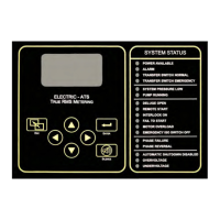
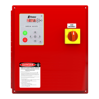
Displays control status, system pressure, frequency, phase, voltage, current, alarms, and timers.
Used to navigate backward through menu screens.
Used to navigate forward and save settings.
Used for up/down menu navigation and value adjustment.
Used to silence audible alarms.
LEDs providing visual indication of important system information.
Configuration for system, date, time, timers, pressure, motor, alarms, features, and options.
Access to event log, data history, USB functions, and factory information.
Configuration for screen, language, units, and passwords.
Settings for date, time, daylight saving, and various operational timers.
Configuration for pressure, motor parameters, alarms, and calibration.
Settings for motor parameters, phase, frequency, FLA, CT ratio, overload, and soft start.
Settings for undervoltage, overvoltage, under/over frequency alarms.
Settings for overpressure, phase imbalance, and motor overload alarms.
Configuration for interlock, low pressure, low suction, and pump run alarms.
Settings for user-defined alarms and automated weekly testing.
Settings for option delay, audible alarms, and common alarm outputs.
Function to save settings, logs, and information to USB.
Visual displays of motor voltage and current during start.
Settings for serial number, model, HP, voltage, FLA, CT ratio, frequency, and phase sequence.
Configuration for pressure sensor, autostart, and user inputs.
Settings for screen saver and ADC calibration.
Access to raw analog and discrete input/output values for troubleshooting.
Functions for checking controller boots and system status LEDs.
Tests for audible alarms, USB, phase failures, and circuit breaker trips.
Options to clear historical data and event logs.
Options to reset settings to defaults or update controller firmware.
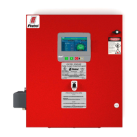
| Type | Fire Pump Controller |
|---|---|
| Model | Mark IIXG |
| Input Voltage | 208-600 VAC |
| Frequency | 50/60 Hz |
| Output Voltage | 208-600 VAC |
| Humidity Range | 0-95% non-condensing |
| Standards | NFPA 20 |
| Operating Temperature | -20°C to 40°C |
| Enclosure Rating | NEMA 3R |
| Dimensions | Varies by model |
| Weight | Varies by model |
| Output Current | Varies with HP rating (See product documentation) |