5. Verify AC line voltage, phase and frequency with the controller data plate on the enclosure door
prior to connecting.
6. Check to see that all connections are both correctly wired (in accordance with the fi eld connec-
tion diagram) and tight.
7. Close the enclosure door.
MAKING SYSTEM PRESSURE CONNECTIONS
The controller requires one (1) “System Pressure” connection from the system piping to the en-
closure. The connection fi tting, 1/2” FNPT, is provided on the bottom, external side of the enclosure
for this purpose.
GENERAL PRE-START UP OPERATION
1. Controllers are shipped with the EMERGENCY RUN handle in the latched position. Before placing
the controller in service, turn the EMERGENCY RUN handle and release to unlatch.
2. Check the controller for bolts, nuts and electrical connections which may have loosened
during shipment.
3. If a remote start push-button is used, connect the wires to terminals as shown on fi eld connection
diagram.
4. If a deluge valve is used, remove the factory installed jumper from terminals as shown on fi eld
connection diagram. Connect wires from the normally closed contact on the deluge valve to
terminals.
5. If a FTA200 remote alarm panel is used, connect like numbered terminals in the remote alarm
panel to terminals in the fi re pump controller. Terminals H and N must be connected if a FTA200
alarm panel is used.
6. If a FTA200 remote alarm panel is used, connect a reliable, separate, supervisory 120
volt power supply to terminals L1 and L2 in the alarm panel.
GENERAL START UP OPERATION
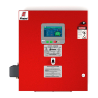
General operating procedures are indicated on the data plate fastened to the front of the control-
ler enclosure door.
Voltage Check—
1. Energize the incoming power feeder.
2. Observe the Mark II
XG screen. Confi rm that the displayed voltage and frequency matches the
voltage stamped on the data plate.
4
At this time, it is necessary to prepare the controller for normal
operation. See setup instructions for the Mark IIXG. After the
Mark IIXG has been configured, return to this section.
 Loading...