2
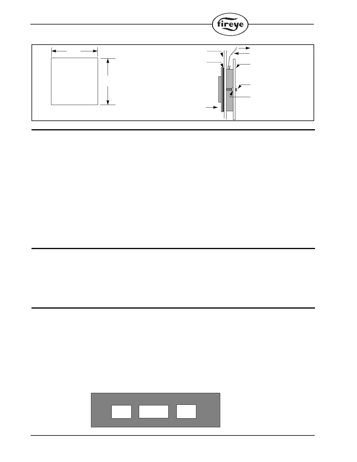
FIGURE 1. INSTALLATION AND MOUNTING DIAGRAM OF ED510 WITH 129-145
ORDERING INFORMATION
P/N DESCRIPTION
ED510 Display module. Includes ED580-1 cable. (1.25 inches).
129-145-1 Remote mounting kit. Includes ED580-4 cable (4 foot).
129-145-2 Remote mounting kit. Includes ED580-8 cable (8 foot)
ED580-1 1.25 inch display cable.
ED580-4 4 foot remote display cable.
ED580-8 8 foot remote display cable.
ED610 Adaptor for cable lengths greater than 8 feet.
Temperature Rating
32 F — 140F (0 C— 60C)
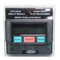
BACKLIT LCD DISPLAY
The ED510 display has a two (2) line by sixteen (16) character backlit LCD display. The backlit
function is continuously energized.
Contrast Control: The contrast for the LCD display is factory set. If the contrast must be adjusted
for any reason (e.g.: remote mounting), a potentiometer is provided on the back of the ED510 display
board.
TACTILE DOME KEYPAD
The ED510 has a three (3) key, tactile dome keypad to review both current and historical information
associated with the operation of the burner. Following is the function of each key:
SCRL SCRL key is used to advance through and display historical and operational information associated with the control and various sub-
menus.
RESET RESET key resets the control in the event of a lockout condition. The reset key is also used to modify Unit Address and messages asso-
ciated with the E300 expansion module.
MODE MODE key selects and enters a sub-menu (e.g. LOCKOUT HISTORY). The SCRL key then advances through the selections within each
sub-menu. The MODE key will also exit the sub-menu. A right-hand arrow () displayed on the bottom line indicates the MODE key is
operational.
KEYPAD/DISPLAY
FRONT
GASKET
PEM NUT
INSIDE
MOUNTING
SCREW
MOUNTING
PLATE
MAXIMUM THICKNESS
CONNECTOR
CABLE (2’, 4’, or 8’)
TO EP/EPD PROGRAMMER
5/64 INCH (2.0mm) PANEL
3.63
(92.0mm)
3.63
(92.0mm)
SUGGESTED PANEL CUTOUT DIMENSIONS