Do you have a question about the Fireye ED510 and is the answer not in the manual?
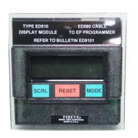
Two-line, sixteen-character backlit LCD display for burner status.
Displays current burner status and first-out annunciation in lockout.
Three-key keypad for historical info, lockout details, and diagnostic messages.
Mounts directly onto the front face of EP style programmers.
RJ style connector for connection to EP and EPD programmers.
Supports remote display with EP, EPD, and MicroM systems.
Weatherproof housing (NEMA 4) with remote mounting kit.
Mounts directly onto the front of EP style programmers, with or without EB700 chassis.
Remove power from the EB700 chassis if the programmer is installed.
Slide the chassis bottom onto mounting tabs and tilt until it snaps into place.
Install the ED580 cable into RJ connectors on the display and programmers.
Insert programmer and display into the EB700 chassis and restore power.
Refer to Bulletin E-8002 for remote mounting information.
Display module including ED580-1 cable (1.25 inches).
Remote mounting kit including ED580-4 cable (4 foot).
Remote mounting kit including ED580-8 cable (8 foot).
1.25 inch display cable.
4 foot remote display cable.
8 foot remote display cable.
Adaptor for cable lengths greater than 8 feet.
Operating temperature range is 32°F to 140°F (0°C to 60°C).
Information on LCD contrast adjustment via a potentiometer on the back.
Advances through historical and operational information and sub-menus.
Resets control during lockout, modifies Unit Address and messages.
Selects and enters sub-menus, exits sub-menus, indicated by a right-hand arrow.
Displays burner status, first-out annunciation, historical info, and diagnostics.
Programmers update messages; ED510 displays "WAITING FOR DATA" if no communication.
Displays operational status messages like Standby, Purge, and Ignition Timing.
Control holds standby for 60 seconds, checking 3-P circuit.
Control holds high purge for 10 mins, waiting for D-8 switch.
Control holds low fire for 10 mins, waiting for M-D switch.
Running interlock (3/P) did not close within 10 secs of purge.
Flame sensed during off time or purge, holds for 60 seconds.
Control waited 60 secs for 3-P circuit to open during standby.
Control held for 10+ mins waiting for D-8 switch to close.
Interlock (3/P) opened during purge or failed to close.
Fuel valve end switch opened during purge or at start up.
Control held for 10+ mins waiting for low fire switch (M-D) to close.
Interlock (3-P) opened during pilot trial for ignition.
Interlock (3-P) opened during main trial for ignition.
Interlock (3-P) opened during main burner on period.
Flame sensed during off time or purge for sixty (60) seconds.
Flame failure occurred during the pilot trial for ignition period.
Flame failure occurred during the main trial for ignition period.
Flame failure occurred during the main burner on period.
Ignition cable noise; reroute scanner wires, check spark gap or grounding.
Excessive current on terminals 5, 6, or 7 during PTFI, MTFI, or Auto.
Voltage on terminal 7 differs from previous cycle during pilot trial.
Electrical noise detected on terminals L1 and L2.
Power interruption to terminals L1 and L2 caused lockout.
"Run-Check" switch in Check position during purge, driving high purge.
"Run-Check" switch in Check position after high fire purge, driving low fire.
"Run-Check" switch in Check during pilot trial; lockout on safety if no flame.
"Run-Check" switch in Check during main burner; drives low fire.
Possible causes: High electrical noise, defective wiring, amplifier, or IR scanner.
Voltage on terminal 7 at improper time; check wiring to terminal 7.
Voltage on terminals 5 or 6 at improper time; check wiring to terminals 5 and 6.
Flame signal detected during shutter close time; stuck shutter.
E300 Expansion Module has a defective optocoupler.
Amplifier has failed diagnostic checks.
SCRL key scrolls through burner cycles, lockouts, system hours; MODE key accesses sub-menus.
Displays last six lockouts, burner cycle and hour; MODE key shows recent lockout.
Programs messages for E300 Expansion Module operation.
Displays programmer type, purge timing, FFRT timing, etc.
Displays control operation info like flame signal strength and switch status.
Modify lockout alarm messages for E300 Expansion Module via ED510 display.
Messages divided into Recycle, Non-recycle, Gas Select, and Oil Select groups.
Use Mode, Reset, and Scroll keys to enter, select, and modify E300 messages.
Messages for recycle group, including E340 Op Cntl Open and Low Water.
Messages for oil select group, including Low Oil Pressure and High Oil Temperature.
Messages for gas select group, including High Gas Pressure and Low Gas Pressure.
Messages for non-recycle group, including High Temperature and Air Flow Open.
Review operational settings like programmer type, purge timing, and flame signal.
Displays the programmer type, e.g., EP160.
Shows the software engineering code of the programmer module.
Identifies the amplifier module, e.g., EUV1 or ERT1.
Indicates purge timing selected by dipswitches.
Shows if "Proven 3-P Open To Start" is enabled or disabled.
Displays Flame Failure Response Time (FFRT).
Shows the Unit Address, e.g., #00.
Review control operation details like flame strength and switch status.
Shows the average flame signal strength of the pilot flame.
Shows the average flame signal strength of the main flame.
Total number of short circuits detected on terminals 5, 6, and 7.
Indicates the status of the high fire end switch (D-8).
Indicates the status of the low fire end switch (M-D).