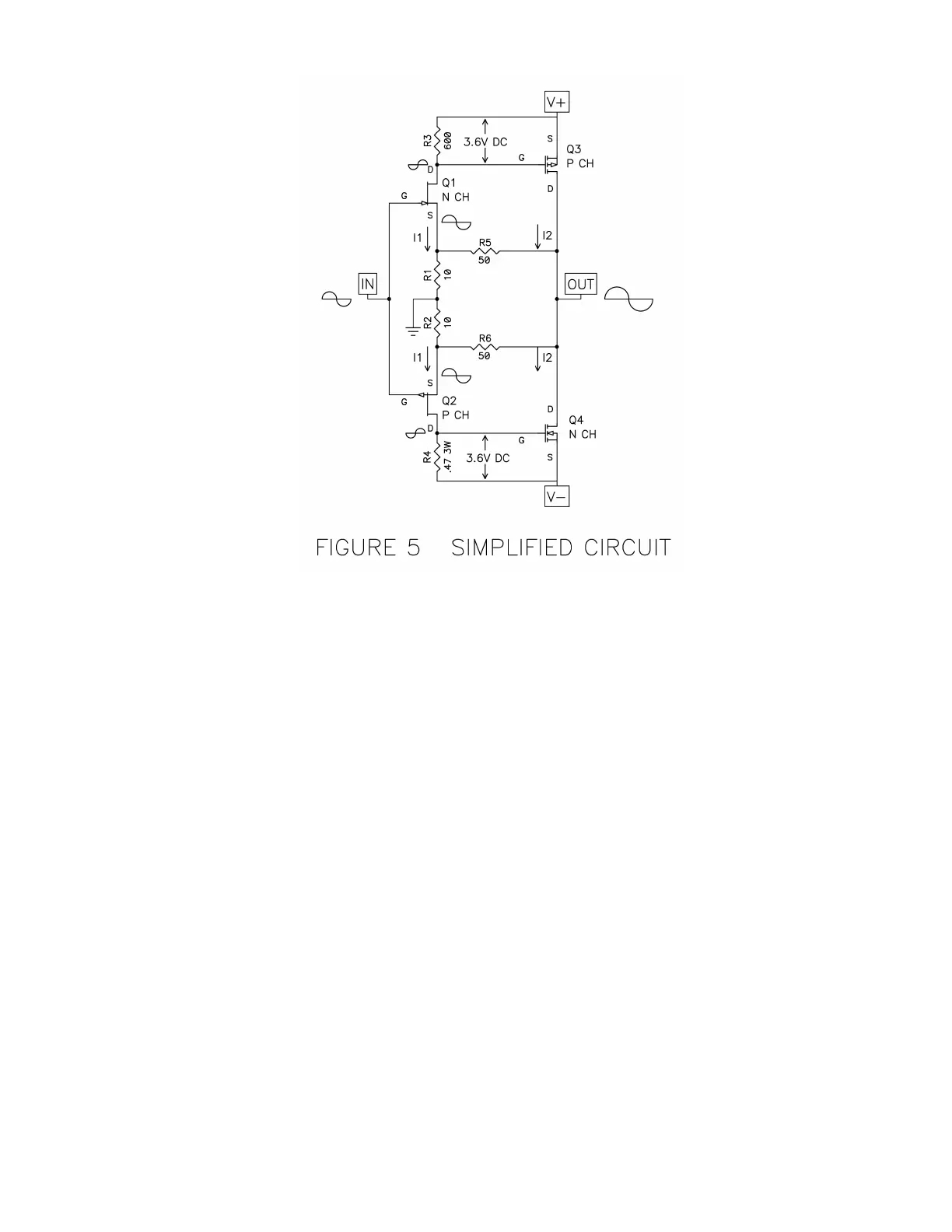
JFETs Q1 and Q2 form a complementary Common-Source stage, with the input appearing
at their Gates and output at their Drains. The JFETS are Class A self-biased at about 6 mA,
and so a current I1 comes out of their Drain connections and creates a voltage of about 3.6
volts across R3 and R4, whose values are about 600 ohms. This 3.6V DC value is
necessary to bias the power MOSFETs Q3 and Q4 into conduction. The voltage gain of Q1
and Q2 appears across each of these resistors for a gain of about 10 each.
The gain of 10 for the input stage comes from the ratio of the 600 ohms divided by the
apparent resistance from the Source to Ground, which is roughly 60 ohms. This 60 ohm
number comes from the inverse of the JFET’s transconductance plus the 10 ohm actual
resistor. The transconductance for a JFET is the ratio of current change against input
voltage change. The gain of this part is typically 0.02 Siemens, or .02 amps per control volt,
and if you invert that you get 50 ohms (R = V/I). So it looks as if there is 50 ohms inside the
part (although there isn’t), and to that we add the 10 ohms of real resistor to get 60 ohms.
Q3 and Q4 do the heavy lifting in this circuit, providing the large output current needed to
drive the loudspeaker. The DC voltage appearing from the Gate to Source of these devices
is about 3.6 volts, and this biases the MOSFETs to about 1.3 amps.
For this sort of circuit, a 1.3 amp bias means that the amplifier will operate Class A to 2.6
amps of output current. To understand this, imagine a condition where Q3 and Q4 are
idling at 1.3 amps, so that all the current is going from the V+ voltage rail to the V- voltage
rail, and none is going through the loudspeaker.
When a positive voltage appears at the Gates of Q1 and Q2, it makes the current through
Q1 increase and the current through Q2 decrease. The resulting voltages across R3 and