the gate needs to be at about -.25V with respect to the Source. We put 47 ohms in series
with the Source, raising its voltage to +.25V and this conveniently allows us to bias the Gate
at 0V DC, or Ground.
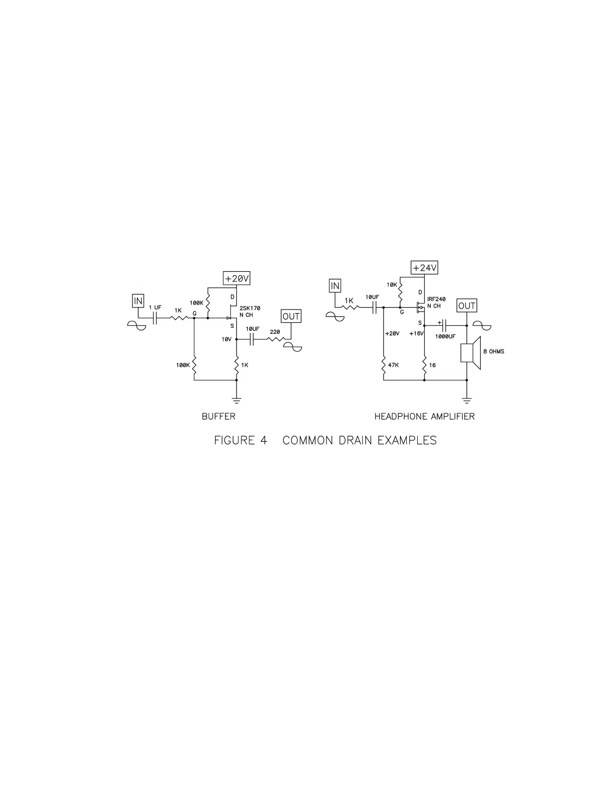
On the right, we have a power MOSFET set up as a simple power amplifier, intended to
deliver about 1 watt into an 8 ohm loudspeaker. The 16 ohm power resistor performs as a
current source to the circuit, and the two 10 Kohm resistors on the input set the DC value for
the Gate to about 4 volts get it to conduct a 1 amp bias current. For a more powerful
version of this, see Zen Variations #1 (AudioXpress, March 2002)
Figure four shows some real Common-Drain amplifiers, a line-level buffer which can be
used in active filters, and a headphone amplifier. In both cases there is no voltage gain in
the amplifier, but there is current gain. They both have high input impedance and low
output impedance.
Common-Gate operation is encountered less often, usually found in “cascode” connection
with another device. Discussions of cascoding with good examples are found in Zen
Variations 8 and 9 (AudioXpress January 2006, May 2006) and also the article “Cascode
Amplifiers” originally published in Audio Magazine, March 1978.
Simplified F5 Circuit
Figure 5 shows the simplest imaginable version possible of the F5. The topology is familiar;
a two-stage conjugate-complementary circuit using two JFET transistors for the input
amplification and two power Mosfet devices for the output.