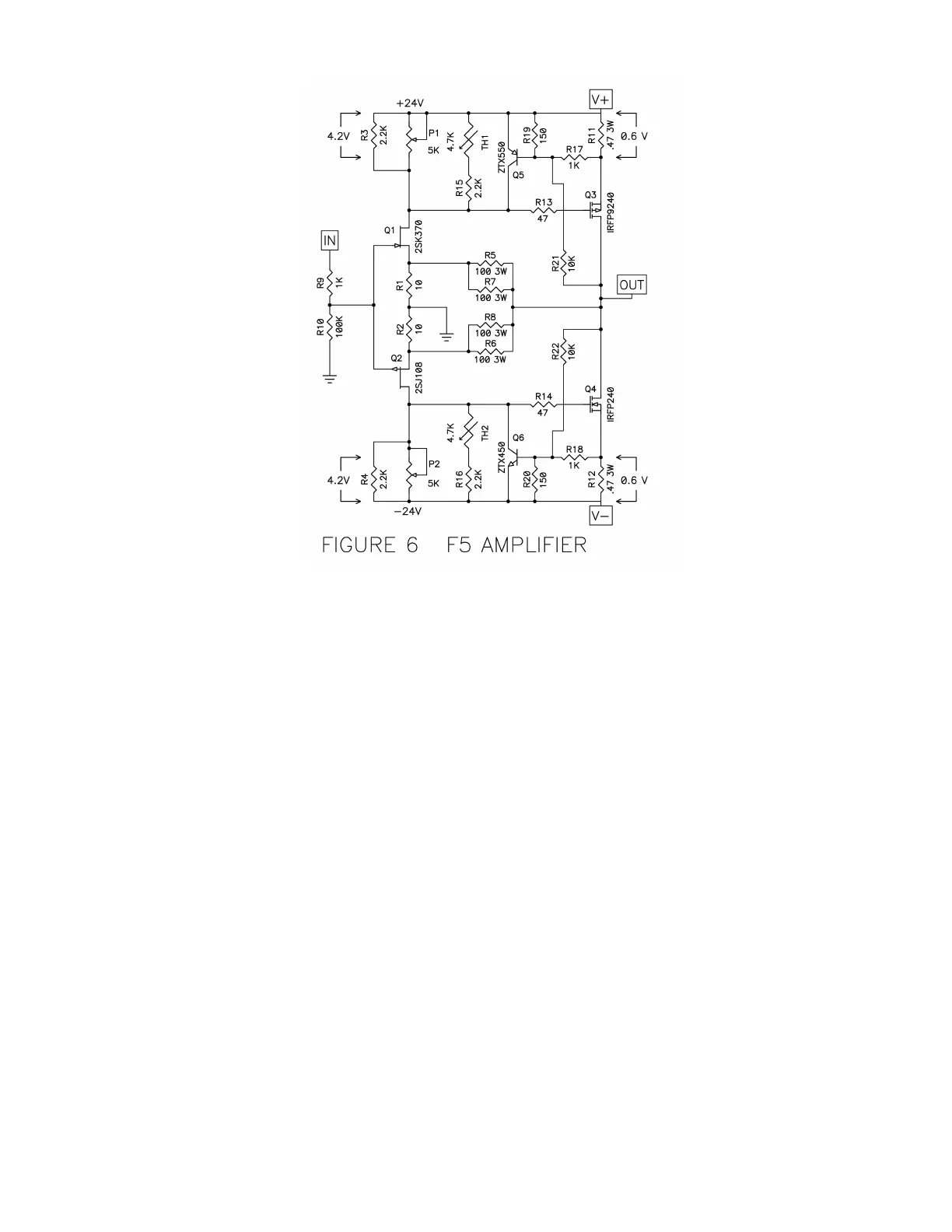
R2 and R4 have had their value increased and then placed in parallel with 5 Kohm trim
potentiometers P1 and P2. This allows adjustment of the output stage bias current and also
the output DC offset.
We can stop here, and the amplifier will be fully functional. The remaining additions will
enhance temperature tracking and provide for output current limiting.
Th1 and Th2 are small 4.7 Kohm thermistors that have been placed in series with R15 and
R16 respectively. The resistance of the thermistor declines with temperature, and if placed
in close proximity to the output transistors will help compensate for thermal drift. You can
build the amplifier without them, but you will have a longer warm-up time and you will spend
more time adjusting the bias.
On the positive half of the output stage, Q5, R17, R19, and R21 will arbitrarily limit the
output of the amplifier in the event that you accidentally set the bias too high or short the
amplifier’s output. Q6, R18, R20 and R22 do the same for the negative half of the amplifier.
The output MOSFETs are easily capable of passing very high currents at the request of Q1
and Q2, and it is wise to set a limit in case of accident.
Understanding the limiting circuit is easy. Q5 and Q6 look at the voltages across the R11
and R12, and will start to conduct when their Base to Emitter voltage exceeds .4 volts or so.
At .4 volts Q5 and Q6 draw off enough drive current from Q1 and Q2 to start creating
measured distortion, and hard limiting occurs when the voltage driving Q5 or Q6 is
increased to .6 volts.