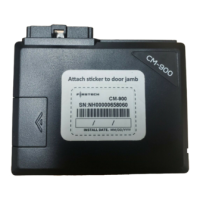
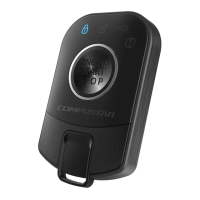
Do you have a question about the Firstech CM900 and is the answer not in the manual?
Instructions for antenna installation and cable management for optimal signal reception.
Details on the FT-Shock dual stage impact sensor installation and sensitivity adjustment.
Step-by-step instructions for programming the DAS II sensor sensitivity and functions.
Explanation of jumper settings for configuring output functions and polarity.
Description of the blue wire's function and its jumper-programmable options.
Description of the green/white wire's programmable output for parking lights or other functions.
Guide to configuring auxiliary outputs using the OP500 programmer.
Simplified procedure for programming the system to use Tach sensing mode.
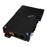
Pinout and function description for the 8-pin main control module connector.
Details for the 20-pin Blade connector used with specific bypass modules.
Pinout and function description for the 18-pin Grey I/O harness.
Information on the 6-pin Connector 4, primarily for Firstech lock harnesses.
Details of the 4-pin UART data port for Drone/Fortin communication.
Description of the 4-pin RS 232 port for module updates and flashing.
Connection details for the optional thermistor temperature sensor.
Connection port for the pre-wired antenna cable.
Connection details for the pre-wired external LED indicator.
Connection port for the pre-wired FT Shock Sensor.
Programming options for features 1-1 through 1-16.
Programming options for features 2-1 through 2-16.
Programming options for features 3-1 through 3-15.
Programming options for features 4-1 through 4-14.
Table listing parking light flash codes for remote start errors.
Codes indicating reasons for remote start sequence shutdown.
Explanation of LED flash patterns for alarm diagnostics.
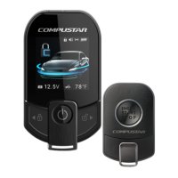
| Operating Voltage | 12V DC |
|---|---|
| Number of Remotes | 2 |
| Remote Start | Yes |
| LED Indicator | Yes |
| Engine Kill | Yes |
| Range | 3, 000 feet |
| Compatibility | Most Vehicles |
| Features | Remote start, keyless entry |
| Operating Temperature | -40°C to 85°C |
| RF Frequency | 433 MHz |
| Security System | Yes |
| Battery Life | Up to 1 year |