Do you have a question about the Firstech CM5200 and is the answer not in the manual?
Procedure to unlock RS232 port for users not using a Blade cartridge.
Steps to verify if CM5000/CM5200 units have the latest firmware.
Information about the manual's purpose and intended users.
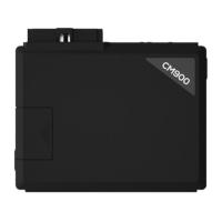
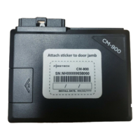
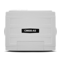
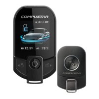
Detailed list of components included with CM5200 and CM5000 control modules.
Warning regarding warranty voidance due to unauthorized installation.
Details for contacting Firstech technical support for authorized dealers.
Essential points to review and address before commencing installation.
Mandatory procedure to code remotes for system functionality.
Instructions for mounting and programming the RPS-II sensor.
Guidance on cutting the green loop for automatic transmission installations.
Steps to learn the vehicle's tach signal for accurate remote start operation.
Overview of expanded option menus available in CM5 series modules.
Instructions for using the OP500 device to set system options.
Information on updating control module firmware via the internet.
Step-by-step guide for programming remotes excluding the P2WSSR.
Specific instructions for programming the P2WSSR remote.
Troubleshooting steps when the vehicle locks/unlocks but won't remote start.
Diagnosing issues when the vehicle chirps three times and fails to arm.
Troubleshooting error codes indicated by parking light flashes on ignition.
Information regarding door lock polarity and compatible modules.
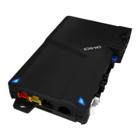
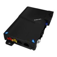
Explanation of the cartridge slot on CM5000 and CM5200 modules.
Answers to common questions about remotes and module types.
Troubleshooting steps for the 'ER 01' error when using the OP500.
Explanation of the green loop wire's role in transmission mode settings.
Guidance on connecting blue and purple wires from the pre-wired relay.
Information on how to access a ground-when-armed wire.
Confirmation of voltage sensing feature in CM5000 and CM5200 modules.
Instructions for configuring auxiliary outputs on the control module.
Guidance on programming the tachometer after all connections are made.
Troubleshooting remote start failures when the system is disarmed but not armed.
Diagnosing remote start sequences that repeatedly shut down.
Guidelines for proper placement and installation of the antenna and cable.
Detailed instructions for RPS-II sensor installation and setup.
Recommendations for mounting and adjusting the shock sensor for optimal performance.
Information on adjusting the siren's output volume and duration.
Details on connecting the optional thermistor for temperature monitoring.
Explanation of jumper settings and their impact on output polarity.
How to set the polarity for the door trigger input using Jumper 1.
How to set polarity for glow plug or key sense input using Jumper 2.
How to configure the output type of the parking light/trunk wire using Jumper 3.
Information on default auxiliary outputs and their customization options.
Tach sensing as the default engine detection method and setup.
Steps for testing the tach wire connection and voltage.
Table of parking light flashes and their corresponding remote start errors.
Explanation of LED flash patterns for diagnosing alarm triggers on CM5000.
Detailed steps for programming options using the OP500 device.
Instructions for programming options using the vehicle's remote.
Confirmation signals for successful tach learning and error code interpretations.
Using alternator sensing as an alternative engine detection method.
Configuring voltage sensing as a tachless mode for automatic transmissions.
Guidance on modifying crank time settings for remote start.
Using Option 2-10 for a 1.5-second timed crank sequence.
Explanation of the green/white loop wire's function for transmission mode selection.
Mandatory setup of reservation mode for manual transmission remote start.
Essential wiring and testing procedures for manual transmission installs.
Step-by-step guide to activate reservation mode for manual transmissions.
Important considerations and notes regarding reservation mode functionality.
Details for options 4-03 through 4-14 related to auxiliary and input functions.
Details for options 2-01 through 2-06 related to engine sensing and timing.
Details for options 2-10 and 2-12 concerning engine sensing and crank duration.
Details for options 3-03, 3-04, 3-06, 3-07 concerning dome light, starter-kill, and siren.
Details for options 3-08, 3-09, 4-01, 4-02 regarding horn and auxiliary outputs.
Explanation of the ADS Blade slot and its role in simplifying installations.
Lists the components included in the Blade system.
Guidance on where to download essential install diagrams for Blade modules.
Warnings regarding improper product care, decomposition, or conversion.
Diagram illustrating the wiring connections for the CM5200 remote start unit.
Details for options 1-01 through 1-04 related to door locking and unlocking.
Details for options 1-05, 1-08, 1-09 concerning rearm, passive arming, and ignition locks.
Details for option 1-11 regarding ignition and accessory pulses upon unlock.
Details for option 1-13 on changing the disarm pulse behavior.
Details for option 1-14 enabling Auto Lock Mode for specific remotes.
Tables detailing programming options for Group 1 features.
Tables detailing programming options for Group 2 features.
Tables detailing programming options for Group 3 features.
Diagram illustrating wiring for the CM5000 alarm and remote start combo unit.
Detailed pinout for the 8-pin Connector 1 (CN1).
Detailed pinout for the 2-pin Connector 11 (CN11) for the thermistor.
Detailed pinout for the 4-pin Connector 12 (CN12) for RS232 data.
Detailed pinout for the 4-pin Connector 7 (CN7) for the RPS.
Detailed pinout for the 4-pin Connector 8 (CN8) for the antenna cable.
Detailed pinout for the 4-pin Connector 10 (CN10) for optional sensors.
Detailed pinout for Connector 3 (CN3), Pins 1-3, the Programmable Output Connector.
Detailed pinout for Connector 3 (CN3), Pins 4-18, the Programmable Output Connector.
Detailed pinout for the 6-pin Connector 4 (CN4).
Detailed pinout for the 2-pin Connector 5 (CN5) for the LED.
Detailed pinout for the 4-pin Connector 6 (CN6) for the shock sensor (CM5000).
Continued pinout details for Connector 7 (CN7) RPS.
Continued pinout details for Connector 8 (CN8) Antenna.
Continued pinout details for Connector 10 (CN10) Optional Sensor Input.
Continued pinout details for Connector 3 (CN3) Programmable Output Connector.
Important note regarding the yellow/black and yellow wires for starter-kill.
Description of CN3 Pin 7 (Green) for ignition 12V positive output and input.
Description of CN3 Pin 8 (Black) for ground negative input.
Description of CN2 Pin 1 (Red) for optional battery back-up power input.
Description of CN2 Pin 2 (Black) for optional battery back-up ground input.
Reference table for programming options within Group 1.
Reference table for programming options within Group 2.
Reference table for programming options within Group 3.
Unlocks doors before remote start to disarm factory alarms.
Adjusts the duration of lock and unlock pulses.
Requires isolated driver's door and specific output configuration.
Provides a double pulse on the unlock wire.
Optional event to shut off RAP systems.
Modifies door locking behavior during passive arming.
Locks doors upon vehicle start and brake pedal press.
Pulses ignition and accessory wires upon unlock/disarm.
Changes the orange/white wire on Connector 3 to a double ground pulse.
Enables Auto Lock Mode for 2 Way international remotes.
Adjusts the method for reading tach by the module.
Adjusts the run time after Turbo mode engagement.
Sets the wait-to-start time for diesel engines.
Changes the number of negative start inputs required.
Dictates the interval between cold start remote starts.
Explains available engine sensing modes: tach, alternator, voltage.
Changes the crank time during the remote start sequence.
Delays door trigger input to prevent door open icons.
Determines the operational mode of the anti-grind/starter-kill relay.
Monitors door triggers and honks horn if doors open while armed.
Adjusts siren duration from 30 seconds to 60 seconds.
Changes horn output behavior during lock, unlock, and start.
Modifies horn behavior when the alarm is triggered.
Determines the duration of the Aux 1 output.
Determines the duration of the Aux 2 output.
Detailed guide on using the OP500 for comprehensive option programming.
Instructions for programming options directly via the remote control.
Steps for changing and adjusting option settings using the OP500.
Procedure for saving programmed option settings using the OP500.
Button combinations for programming options using 2-way remotes.
Button combinations for programming options using 1-way remotes.
Confirmation signals and error interpretation for tach learning.
Table detailing parking light flashes and their corresponding remote start errors.
Explanation of LED flash patterns for diagnosing alarm triggers on CM5000.
Answers to common installation and operational queries.
Answers to common questions about remotes and module types.
Troubleshooting steps for the 'ER 01' error when using the OP500.
Explanation of the green loop wire's role in transmission mode settings.
Guidance on connecting blue and purple wires from the pre-wired relay.
Information on how to access a ground-when-armed wire.
Confirmation of voltage sensing feature in CM5000 and CM5200 modules.
Instructions for configuring auxiliary outputs on the control module.
Guidance on programming the tachometer after all connections are made.
Troubleshooting remote start failures when the system is disarmed but not armed.
Diagnosing remote start sequences that repeatedly shut down.
Guidelines for proper placement and installation of the antenna and cable.
Detailed instructions for RPS-II sensor installation and setup.
Recommendations for mounting and adjusting the shock sensor for optimal performance.
Information on adjusting the siren's output volume and duration.
Details on connecting the optional thermistor for temperature monitoring.
Step-by-step guide for programming remotes excluding the P2WSSR.
Specific instructions for programming the P2WSSR remote.
Troubleshooting steps when the vehicle locks/unlocks but won't remote start.
Diagnosing issues when the vehicle chirps three times and fails to arm.
Troubleshooting error codes indicated by parking light flashes on ignition.
Information regarding door lock polarity and compatible modules.
Explanation of the cartridge slot on CM5000 and CM5200 modules.
Details for contacting Firstech technical support for authorized dealers.
Recommendation to thoroughly review the manual for new installers.
Essential points to review and address before commencing installation.
Mandatory procedure to code remotes for system functionality.
Instructions for mounting and programming the RPS-II sensor.
Guidance on cutting the green loop for automatic transmission installations.
Steps to learn the vehicle's tach signal for accurate remote start operation.
Overview of expanded option menus available in CM5 series modules.
Instructions for using the OP500 device to set system options.
Information on updating control module firmware via the internet.
| Operating Voltage | 12V DC |
|---|---|
| Operating Temperature | -40°C to +85°C |
| RF Frequency | 433 MHz |
| Number of Remotes | 2 |
| Data-to-Data Capable | Yes |
| Compatibility | Most vehicles |
| Remote Start | Yes |
| Alarm Integration | Yes |
| Starter Disable | Yes |
| LED Status Indicator | Yes |
| Operating Frequency | 433 MHz |
| Range | Up to 3000 feet |
| Features | Keyless entry, remote start, trunk release |
| Security Features | Starter kill |
| Type | 2-Way Remote Starter |