Installation Basics
If you are new to installing Firstech Series Remote Starts and / or Alarms, we highly recommended that
you thoroughly review this manual to installing your first unit.
Key Points to Consider Before Installation:
You must code remotes to this system before anything will function
Program remotes by cycling the ignition ON / OFF five times within seven seconds and tap button 1 (0.5
seconds) on the first remote, and then tap button 1 (0.5 seconds) on the second remote.
RPS-II (Remote Paging Sensor)
All 2 Way units include an optional RPS that has three main functions; 1. Status LED, 2. Remote
notification when triggered, and 3. Auto unlock/alarm disarm when a user specific 4 digit knock code is
entered via tapping sensor through the windshield.
Internal green loop must be cut for AUTOMATIC transmission vehicles
By default, CM5 series units come in MANUAL transmission mode. You will need to cut the green loop
inside the control module if you are installing the unit in a AUTOMATIC transmission.
Different tach learning procedure
Learn tach by: 1. Starting the vehicle with the key, 2. Pressing and holding the foot brake, and 3. Holding
the remote start button on the remote for 2.5 seconds - one chirp and parking light flash indicates that the
vehicle tach signal has been successfully learned. Three chirps indicate that the CM4 or CM5 control
module failed to see a proper tachometer signal. (These units have the option for Voltage / Tachless and
1.5 second assume cranking).
New Option Menus
The option menu is larger than the previous CM3 series control modules. It is important to familiarize
yourself with the new options as it will save time in most applications. For instance, Option 1-04 controls
the double pulse unlock feature on all CM5 series control modules.
Option Programmer (OP500)
Most options on these units can be programmed with the remote(s), however setting auxiliaries and
Special Option Groups 1 and 2 require the use of the OP500. Please note, the system must be unlocked
/ disarmed to sync the OP500 with the control module. Otherwise, an “ER 01” message will show on the
display of your OP500.
Internet updatable processors
Visit “Dealer Support” at www.compustar.com
All CM4 and CM5 series units are equipped with some of the most powerful processors available today.
This flexibility allows for on-demand internet updating capabilities in the event of a version update or
change.
4
A: The remotes need to be programmed. Review the “Common Procedure” section of this manual.
I have these control modules that say MM720 and MM721. What are they?
A: These control modules are the new CM5 series. MM720 = CM5000 and MM721 = CM5200.
I am trying to program the control module with the OP500 Option Programmer and it flashes “ER
01” when I plug it in to the antenna cable. What should I do?
A: Make sure that the system is not locked/armed. The last thing to check is the antenna cable or
antenna extension cable – make sure this is not damaged. If you need to, try another cable. When the
OP500 is working properly, it will read “success good.” You no longer need to program the remotes
before the OP500 will sync.
What is the green loop wire inside the brain module?
A: This wire determines the transmission mode. With the loop intact, the system is set for manual
transmissions. With the loop cut, the system is set for automatic transmission.
Where do the blue and purple wires off the extra relay go on the CM5000/CM5200?
A: This is a pre-wired positive output, negative trigger relay. Use the secondary ignition, starter, and
accessory outputs from CN3 to give a negative trigger to the purple wire. This will determine the12V
positive (+) output of the blue wire, which you can then connect to your secondary ignition, starter, or
accessory wire.
I need a ground when armed wire, does the control module have one?
A: You can use the starter output on CN1 that goes to the starter kill relay. You must cut this wire and
place a diode in line so that when the ignition on the other side of the relay goes to ground, it won’t back
feed to your accessory. Install the stripe side of the diode facing the control module.
Are the CM5 series control modules voltage sensing?
A: Yes. The CM5000 and CM5200 all have voltage sensing. Review the “Common Procedures” section
of this manual.
On the brain, how do I set the auxiliaries?
A: Aux 1 and 2 are default on this control module. Aux 1 is the small white wire on Connector 3. Aux 2 is
the small violet wire in Connector 4.
All my connections are made and remotes programmed, how do I program the tach?
A: Review the “Common Procedures” section of this manual.
The vehicle remote starts when disarmed, but not when armed.
A: The starter kill relay was installed backwards. Check to make sure the yellow/black wire is going to the
ignition side of the wire, and that the yellow wire is going to the engine side.
The vehicle starts and shuts down 3 times in a row.
25
Placement and Use of Components
IMPORTANT: The placement and use of components are critical to the performance of this system.
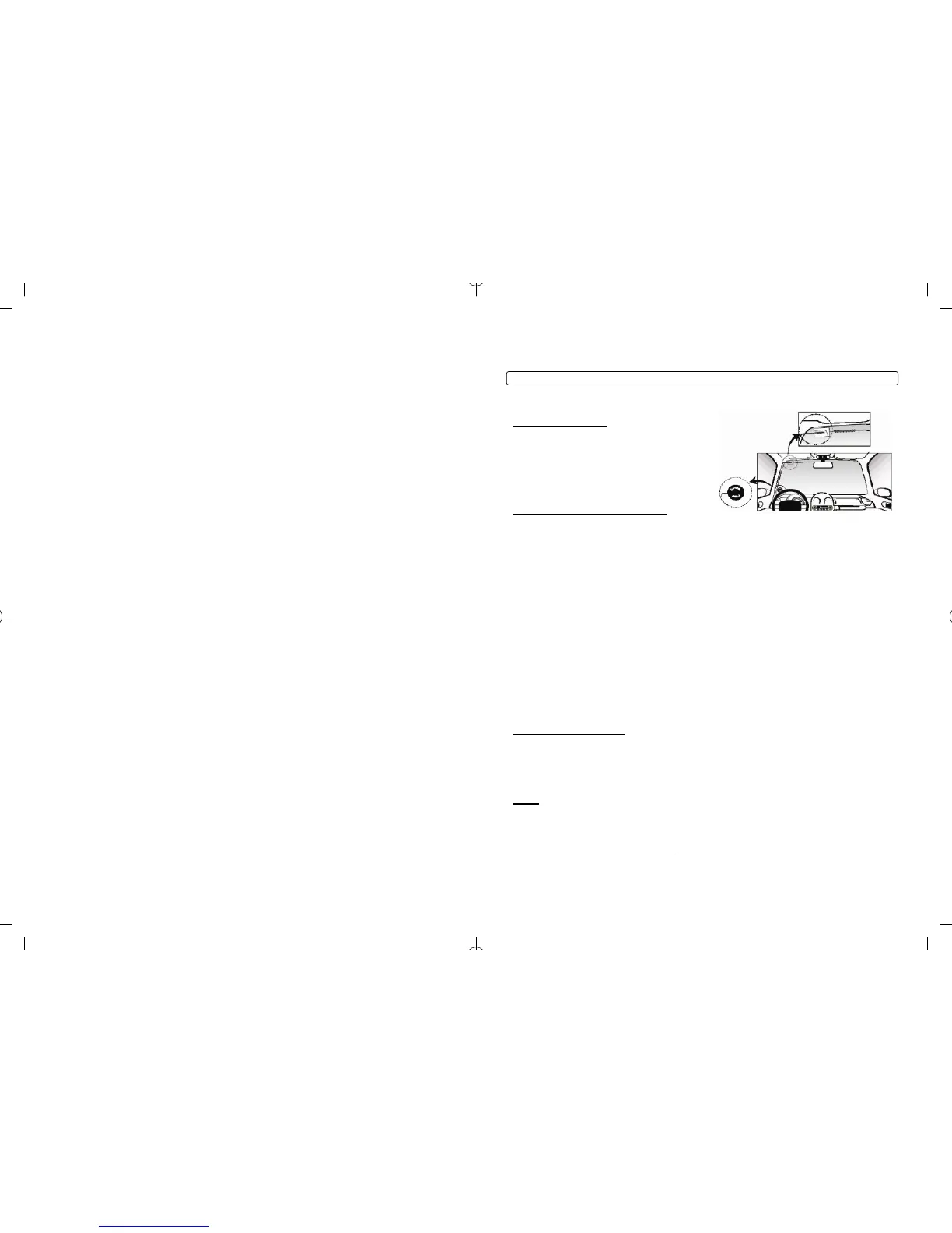
Antenna and Cable
Antenna
Firstech antennas are calibrated for horizontal
installation at the top of the windshield. The cable that
connects the antenna to the control module must be
free from any pinches or kinks. Installing the antenna in
areas other than the windshield may adversely affect
the effective transmitting distance of the remotes.
RPS-II
RPS-II (Remote Paging Sensor)
(CM5000 Only) The RPS-II sensor is designed to be mounted on the inside of the windshield. Basic RPS
functions do not require programming. There is a three position switch on the rear of the RPS-II. This
adjusts the sensitivity of the RPS-II. The larger the circle the more sensitive the knock is. To activate the
RPS unlock / disarm feature you must perform the following procedures:
STEP 1: Disarm/unlock the alarm. (Remotes must be programmed first.)
STEP 2: Turn ignition key to the “on” position and the leave the driver’s door open.
STEP 3: Knock on the windshield in front of the RPS a total of 10 times (each time you knock the LED on the RPS will flash
RED). The LED will begin to flash rapidly in BLUE with successful completion of this step.
STEP 4: Enter the first digit of the desired four-digit pass code by knocking on the windshield in front of the RPS the desired
number of times. For example, to enter 3, knock on the sensor 3 times (each time you knock the LED will flash RED) then wait.
STEP 5: The LED on the RPS will confirm your first number by flashing BLUE slowly. Once the LED begins to flash rapidly in
BLUE, enter your second number by repeating step 4.
STEP 6: Repeat steps 4 & 5 to enter all four numbers.
STEP 7: Turn the ignition OFF. The RPS disarm/unlock feature is now programmed. Repeat steps 3 – 5 to enter your
disarm/unlock code.
**The first two digits of the RPS unlock/disarm pass code will be the default pass code for the Secure Valet (you do not
need to program them independently).
Firstech Shock Sensor
(CM5000 Only) For best results mount the shock sensor by zip tying it to the vehicle’s main ignition
harness. There is a small dial on the sensor that ranges from Off to 10. The higher the number on the
dial the greater sensitivity of impact. A small adjustment to the dial can make a significant difference in
sensitivity for both 1
st nd
and 2 stages. Recommended dial settings for most vehicles is somewhere
between 2 & 4.
Siren
(CM5000 Only) The volume output of the siren can be increased 3 dB by cutting black wire loop located
near the base of the siren. To adjust duration time when the alarm has been triggered, change Option 3-
07 – the system default is 30 seconds.
Thermistor (Temperature Sensor)
Every 2 Way remote - Firstech system includes an optional thermistor, which must be plugged into the 2
pin port of the control module for use. This plug is blue on the CM5000. The use of the thermistor allows
6
STEP 2: To change the option number you wish to program, use the left and right arrow keys on the
OP500. It will scroll through the options available in menu 1 and then move to menu 2, then 3 and 4. Use
the up and down arrow buttons on the OP500 to adjust the option settings; “1” is the default setting, and
“2”, “3”, and “4” are the optional settings.
At the end of menu 4, if diesel mode or channel expander functions were enabled – or if any of the
auxiliary outputs were set to “Program”, the duration of these settings can now be adjusted.
STEP 3: When finished with the adjustment of the various option settings, press and hold the “W” (write)
button until the OP500 chirps, which is approximately 2.5 seconds. This will write the settings to the
control module. Wait until the module displays “Success” before disconnecting it from the antenna cable.
To reset the options, hold the “R” (reset) button and the “W” (write) button for 2.5 seconds. Release then
write the reset, hold the “W” button until the OP500 chirps, which is approximately 2.5 seconds.
Option Programming Using a Remote
Using a remote is a timed process so read this section in its entirety before beginning. IMPORTANT:
Special Option Groups cannot be programmed with a remote – the OP500 must be used.
STEP 1: Select the option menu that contains the desired programming option.
To program options use the following button combinations:
How
To Program Options
With 2 Way Remotes
Scroll
Select Select Select Select
With 2 Way Remotes
Through
Menu
Option 1 Option 2 Option 3 Option 4
(1 + 2) for 2.5 seconds then
(1 + 2) for 2.5 seconds
Tap Button
4
Tap Button
1
Tap Button
2
Tap Button
3
Tap Button
4
Option Menu 1
(1 + 2) for 2.5 seconds then Tap Button Tap Button Tap Button Tap Button Tap Button
Option Menu 2
(1 + 4) for 2.5 seconds 4 1 2 3 4
(1 + 4) for 2.5 seconds then
(1 + 2) for 2.5 seconds
Tap Button
4
Tap Button
1
Tap Button
2
Tap Button
3
Tap Button
4
Option Menu 3
(1 + 4) for 2.5 seconds then Tap Button Tap Button Tap Button Tap Button Tap Button
Option Menu 4
(1 + 4) for 2.5 seconds 4 1 2 3 4
How To Program Options With 1 Way Remotes
Scroll
Select Select Select Select
With 1 Way Remotes Through
Menu
Option 1 Option 2 Option 3 Option 4
Hold Trunk
+ Key/Start
for 2.5
seconds
Hold Trunk
+ Key/Start
for 2.5
seconds
Tap
Unlock
Button
Tap
Key/Start
Button
Lock + Unlock for 2.5
seconds then Lock + Unlock
for 2.5 seconds
Tap Lock
Button
Option Menu 1
Hold Trunk Hold Trunk
Lock + Unlock for 2.5 Tap Tap
Tap Lock
Option Menu 2
seconds then Lock +
Key/Start for 2.5 seconds
+ Key/Start + Key/Start
for 2.5
seconds
Button
Unlock Key/Start
for 2.5
Button Button
seconds
Hold Trunk
+ Key/Start
for 2.5
seconds
Hold Trunk
+ Key/Start
for 2.5
seconds
Tap
Unlock
Button
Tap
Key/Start
Button
Lock + Key/Start for 2.5
seconds then Lock + Unlock
for 2.5 seconds
Tap Lock
Button
Option Menu 3
Hold Trunk Hold Trunk
Lock + Key/Start for 2.5 Tap Tap
Option Menu 4 seconds then Lock +
Key/Start for 2.5 seconds
+ Key/Start Tap Lock + Key/Start
for 2.5
seconds
Button
Unlock Key/Start
for 2.5
Button Button
seconds
23
 Loading...