st
Pin 4 Grey/White - 1 stage negative (-) input. (Warn away)
Connector 11 (CN11), 2-Pin (Pre-wired Thermistor)
Plug optional thermistor into this connector to monitor the vehicles’ temperature. It used display
temperature on two way LCD’s. IMPORTANT: New Thermistor plugs are blue 2 pin connectors on the
CM5 series but old white plug Thermistors will still work.
Black
Pin 1
- Thermistor
Black/WhitePin 2 - Thermistor
Connector 12 (CN12), 4-Pin (RS 232 Data Port)
This connector is used for updating control modules via www.compustar.com. You must also use this
port to flash ADS Blade bypass modules. This port provides simple connectivity of Fortin and iDataLink
bypass modules.
18
11
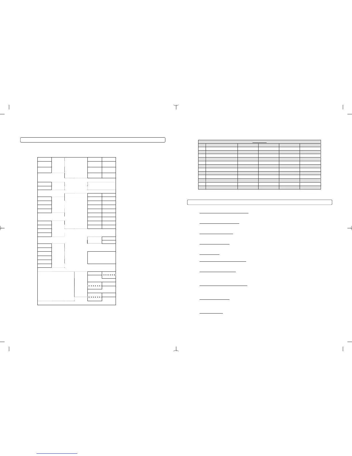
CM5200 Wiring Schematic (Remote Start)
The CM5200 is the control module for all remote start units. This controller is universal regardless of
remote or antenna type.
( - ) Switch 3 Gray 1 Red
2 Green /
White
1: ( + ) 12v Constant 2: ( + ) Parking Light
( + ) Led 2 Gray 3 Red/White 4 White
3: ( + ) 12v Constant Red / White
prewired to 2
nd
Relay
4: ( + ) Accessory
( - ) Led 1 Gray/Black
CN9
Plug In
LED/Valet
Switch
(N/A on
V.SF)
5 Violet 6 Yellow
5: ( - ) When Armed prewired to
Anti-Grind Relay
6: ( + ) Starter prewired to
Anti-Grind Relay
CN1
7 Green and
Red
8 Black
7: ( + ) Ignition Red prewired to
Anti-Grind Relay
8: ( - ) Ground
LED ( + ) Black / White
LED ( - ) Black
CN5
LED
ADS Blade Connector
(20 Pin Harness)
Please see the installation manual
for the Blade module for details.
This harness is not
included with the CM5200.
1 Green / White 2 Lt Blue 1: ( - ) Parking Lt. Output 2: ( - ) E-Brake Input
( - ) 4 Black 3 Red / Black
4 Lt. Blue /
White
3: ( - ) Starter Output 4: ( + ) Brake Input
( + ) 3 White 5 Green 6 Violet / Black 5: ( - ) Ignition Output 6: ( - ) Trunk Input
TX 2 Red 7 White / Black 8 Red / White 7: ( - ) Accessory Output 8: ( - ) Door Input
RX 1 Yellow
CN8
Antenna
9 Black
10 Brown /
White
9: ( - ) Status Out (GWR)
10: ( - ) Glow Input/Key
Sensing
11 Orange 12 Pink 11: ( - ) Rearm Output
12: ( - ) Slave/Closed Loop
Input
13 Orange /
White
14 Yellow /
Black
13: ( - ) Disarm Output
14: (AC) Tach / Alternator
Input
4 ( - ) 15 White
16 Gray /
Black
15: ( - ) Aux 1 Output 16: ( - ) Hood Input
3 ( + )
CN3
17 Violet 18 Brown 17: ( - ) Aux 2 Output 18: ( + ) Siren Output
2 Data
1 Data
CN12
RS232
1 Black / White
CN11
Thermistor
2 Black
( + ) 12v
Constant Power
None
( - ) Lock Output 5 Blue / Black
( - ) Unlock
Output
4 Blue
( - ) Second
Unlock Output
3 Orange /
Black
( - ) Trunk
release output
2 Violet /
White
Green/White Loop
Cut=Auto Trans. Uncut=Manual
Trans.
Every control module has this wire
intact and must be cut for automatic
Future use None
CN4
( + ) ( - )
Default
Door Trigger Polarity
( + ) ( - )
Default
Key Sense/Glow Plug Polarity
Jumpers
( + ) Parking
Lights
Trunk Release
Blade Cartridge Slot - Please visit
www.idatalink.com/compustar for
compatibility and more information. This
slot is empty and has a plastic cover that
slides off.
IMPORTANT: Manufacturer or seller will have
no responsibility for any injuries and/or
damages caused by improper care of the
product such as decomposition, conversion,
and transform done by a user voluntarily.
Default
Behavior of CN1, Pin 2
OPTION GROUP 4
Feature Default Setting - I Optional Setting - II Optional Setting - III Optional Setting - IV
4-01 Aux 1 output 0.5sec Latch Program
4-02 Aux 2 output 0.5sec Latch Program
4-03 Aux 1 output Control Aux 1 Horn Status
4-04 Aux 2 output Control Aux 2 Dome Light Defrost
4-05 Secure Aux Output (1 and 2 Only) On Off
4-06 Auxiliary Input 1 Prewarn Trigger (-) Disarm
4-07 Auxiliary Input 2 Trigger Prewarn (-) Arm
4-09 Key Sense or Glow Plug input Glow Plug Input Key Sense Input
Bypass Through RS232 Port (Only
Available on CM5000)
4-11 ADS Fortin
nd nd nd nd
4-12 2 Ignition 2 Ignition 2 Accessory 2 Starter Ground When Armed
nd nd nd nd
4-13 2 Accessory 2 Accessory 2 Starter 2 Ignition Horn
nd nd nd nd
4-14 2 Starter 2 Starter 2 Ignition 2 Accessory Dome Light
Option Menu Descriptions
Unlock Before, Lock After Starting
1-01
– This option unlocks the door before remote starting to
disarm the factory alarms.
Lock/Unlock Pulse Duration
1-02
– This option changes the duration that both lock and unlock wires
pulse. Please see the above option table for available options.
Driver’s Priority Unlock
1-03
- The driver’s door must be isolated from the other doors. Use the
Orange/Black CN-4 as your 2
nd
Unlock output.
Double Pulse Unlock1-04 – This feature cannot be used with Option 1-03. This feature provides a
double pulse on the blue unlock wire.
Rearm Output
1-05
– Optional event to shut RAP systems off.
Locking while in Passive Arming
1-08
– This option changes the behavior of the lock during Passive
mode. With the optional setting the doors will not lock during Passive arming.
Ignition Controlled Locks
1-09
– This feature locks the doors when you start the vehicle and press
the foot brake. You must also turn this feature on through the remote by tapping I+IV (2 Way
remotes) or Lock+Key (1 Way remotes)
Ignition / Accessory Upon Unlock
1-11
– This option will pulse the ignition wire, accessory, or both
upon unlock/disarm. Most new Chrysler vehicles need the ignition and accessory pulsed to
disarm the factory alarm.
Double Pulse Disarm
1-13
– This option changes the behavior of the orange/white wire on Connector
3. At default the wire will pulse once upon disarm. This option will change it to double ground
pulse upon disarm.
1-14
Auto Lock Mode – This option must be set for the Auto Mode on 2 Way international remotes to
function.
20
(manual transmission) mode, the system must be set up in Reservation mode prior to the vehicle being
able to remote start. IMPORTANT: All warranties or claims are void if a controller with a cut loop is
installed on a vehicle with a manual transmission.
Reservation Mode for Manual Transmissions
To remote start a manual transmission vehicle, the system must first be set up in reservation mode.
Reservation mode is designed to prevent the vehicle from remote starting while the transmission is in
gear.
Installation Requirements
1. The vehicle’s door triggers must be connected to the control module. Prior to making final connections,
test the factory door triggers to ensure that they are functioning properly.
2. The vehicle’s emergency/parking brake wire must be connected to the control module. The proper
vehicle wire usually provides a negative (-) trigger while the emergency / parking brake is set.
3. The vehicle’s clutch must be momentarily bypassed while the remote start cranks the engine. This
momentary bypass simulates the clutch being depressed. For complete details on how to wire a
momentary clutch bypass consult your CompuTech program or contact our technical support department
by calling 888-820-3690.
IMPORTANT: Do not install a remote start in manual transmission vehicles with convertible / removable
tops and in user’s vehicles that leave their windows down. Firstech nor their authorized dealers will
assume responsibility for improper use or install.
Activating Reservation Mode
STEP 1: Start the vehicle with the key. Place the transmission in neutral, remove pressure from the
pedal brake, and set the emergency/parking brake.
STEP 2: Remove the key from the vehicle’s ignition. The vehicles engine should remain running even
after the key has been removed. If the vehicle does not remain running, check the emergency / parking
brake connection.
STEP 3: Exit the vehicle and close the door. The vehicle’s engine should shut off upon closing the door.
If the vehicle’s engine does not shut off, check the door trigger connection or wait for the factory dome-
light to go out. The Firstech system is in reservation mode and the vehicle is ready to safely remote start.
Additional Notes
Reservation mode will be cancelled if the control module recognizes the vehicles door, hood or trunk
opening – or if the alarm is triggered. Each time the end user wants to remote start their manual
transmission vehicle, they must set the control module in reservation mode. Reservation mode settings
can be programmed with Option 1-06.
9
 Loading...