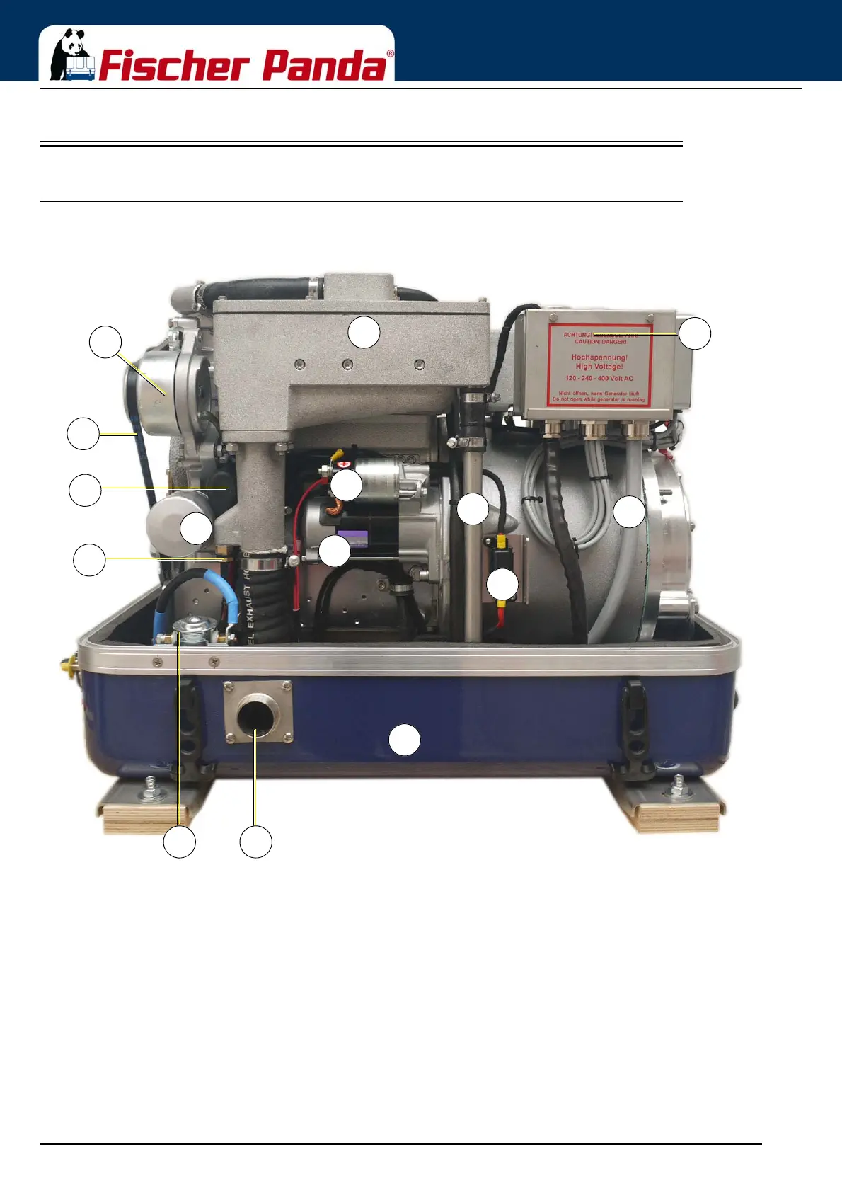
Fig. 4.2.1-1: Right Side View
01. Water-cooled exhaust manifold / Heat exchanger (inside)
02. DC-alternator
03. V-belt for DC-alternator and cooling water pump
04. Oil pressure switch
05. Magnetic switch for starter motor
06. Starter Motor
07. Engine oil filter
08) Thermo sensor at exhaust
09. Flat fuse
10. Ground isolation relay (option)
11. Exhaust connection
12. Sound-cover base part
13. Cooling water return line
14. Generator housing with winding
15. Generator power terminal box