10
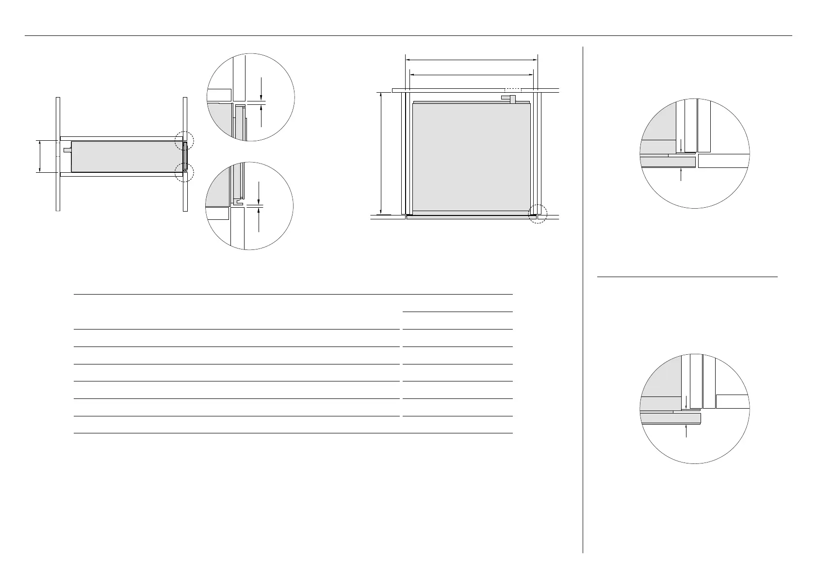
CABINETRY DIMENSIONS - 600MM MINIMAL & CONTEMPORARY MODELS
PROUD INSTALL
FLUSH INSTALL
PLAN
c
b
d
PO*
PROFILE
a
PO*
e
f
CABINETRY DIMENSIONS
WB60SDE
MM
A Minimum inside height of cavity 142
B Minimum inside width of cavity 560
C Minimum inside depth of cavity 572
D Overall width of cabinetry 600
E Minimum clearance between top of front panel and upper cabinetry panel 3
F Minimum clearance between bottom of front panel and lower cabinetry panel 2
* The power outlet (PO) must be earthed and located within 900mm of the centre rear of the product.
Actual product dimension may vary by ± 2 mm.
13/16 (20mm)
13/16 (20mm)

 Loading...