599266B
10
5. Ignition, flame sensing and auto reignition
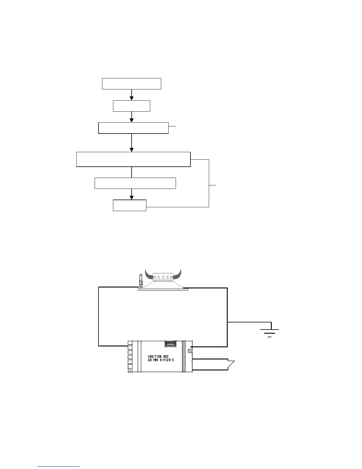
5.1 Ignition sequence
5.2 Flame sensing
The ignition box senses when a flame is lit using flame rectification current sensing. The AC
voltage supplied from the ignition box is rectified to a DC current that is monitored at the ignition
box. This is achievable due to the characteristics of the electrical circuit created by the ignition
box, electrode, flame and burner.
Note: There is a cam in each switch in the ignition switch loom and a specific electrode location
at the ignition box for each burner. This identifies to the ignition box which burner to flame
sense. For this reason the electrodes cannot be swapped between burners. (refer to Section 4
or 6.4 for the correct electrode location and the corresponding burner)
AC voltage
DC current flow
Earth
Burner knob is turned on
LED turns on
Ignition box does a self check
Shut off solenoid is energised allowing gas to flo
into the manifold and through the gas tube
Ignition starts (all electrodes spark)
Burner is lit
Takes approximately 2 seconds
Takes approximately 2-3
seconds.
If the burner doesn’t light within
approximately 5 seconds a fault
condition will occur.

 Loading...