23
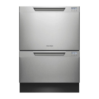
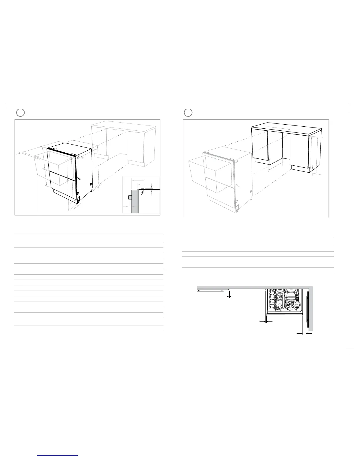
PRODUCT DIMENSIONS CABINETRY DIMENSIONS
N
B
C
E
D
F
J
G
H
M
I
Installation diagrams for illustration purposes only
K
L
A
M
G
C
I
Product dimensions (inches (mm))
Pre nished
LCD
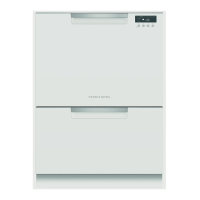
DD24D
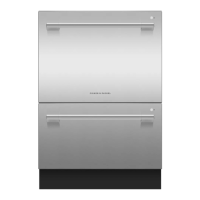
Pre nished
Flat door
DD24D
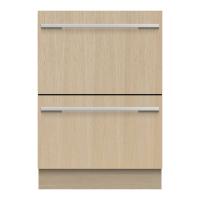
Integrated
DD24D
A
overall height* of product
32 ¼ - 34 ⁄”
(819.5- 879.5)
32 ¼ - 34 ⁄”
(819.5- 879.5)
32 ¼ - 34 ⁄”
(819.5- 879.5)
B
overall width of product 23 ⁄”(599) 23 ⁄”(599) 23 ⁄”(599)
C
overall depth of product (excl. curvature/handle) 22 ⁄” (570) 22 ⁄” (570) 22 ⁄” (570)
D
depth of drawer (open) (excl. curvature/handle) 21 ⁄” (538) 21 ⁄” (538) 21 ⁄” (538)
E
height* of chassis 31 ⁄” (809) 31 ⁄” (809) 31 ⁄” (809)
F
height range of levelling feet 2 ⁄” (60) 2 ⁄” (60) 2 ⁄” (60)
G
depth of chassis (incl. trimseal) 21 ¾ ” (552) 21 ¾ ” (552) 21 ¾ ” (552)
H
depth of drawer front panel (excl. curvature/handle) ⁄” (18)
⁄” (18) ⁄” (18)
I
depth of curvature or handle ⁄” (11) 1 ⁄” (41)
n/a
J
depth of toekick 2 - 4 ⁄” (50 - 110) 2 - 4 ⁄” (50 - 110) 2 ⁄ - 5”(67 - 127)**
K
height of upper drawer front 15 ½ ” (394) 15 ⁄” (398) 15 ⁄” (398) min
L
height of lower drawer front 14” (356) 14” (356) 12 ¼ ” (311.5) min
M
height of installation bracket slots (on top of chassis) ⁄” (2) ⁄” (2) ⁄” (2)
N
height of drawer fronts 29 ⁄” (751) 30 ⁄” (764) 28 ¼ ” (717.5) min
* Chassis heights include bracket slots
** less the Toekick Panel thickness (Minimum Panel thickness using the supplied screws is
⁄” (9 mm)).
Note: for Pre nished Flat door models, height from top of handle to top of drawer -
2 ½ ” (64 mm).
Cabinetry dimensions (inches (mm))
Pre nished
LCD
DD24D
Pre nished
Flat door
DD24D
Integrated
DD24D
A
inside height of cavity
32 ⁄ - 34 ¾ ”
(820- 882.5)
32 ⁄ - 34 ¾ ”
(820- 882.5)
32 ⁄ - 34 ¾ ”
(820- 882.5)
B
inside width of cavity
23 ⁄” (600) 23 ⁄” (600) 23 ⁄” (600)
C
inside depth of cavity (inside)
22 ⁄” (580) 22 ⁄” (580) 22 ⁄” (580)
D
height of adjacent cabinetry 30” (762) 30” (762) min. 28 ⁄” (720)
E
height of toekick space
3 ⁄ - 6 ⁄” (100-160) 3 ⁄ - 6 ⁄” (100-160) 3 ⁄ - 6 ⁄” (100-160)
Minimum clearances (inches (mm))
⁄” (2.5 mm)
⁄” (2.5 mm)
A
B
C
D
E
Installation diagrams for illustration purposes only
½ ” (13 mm)
(1,2) -1- 599618C DD24D install A2 USCA.indd 15/4/09 10:01:39 AM
(1,2) -1- 599618C DD24D install A2 USCA.indd 15/4/09 10:01:39 AM

 Loading...