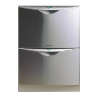
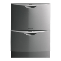
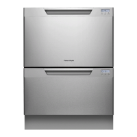
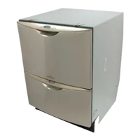
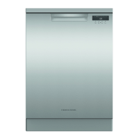
The Fisher & Paykel DishDrawer is a unique dishwasher designed for ease of use and efficient cleaning. It is available in single and double drawer configurations, with models including DD602, DD602I, DS602, and DS602I.
Function Description
The DishDrawer operates with a fully electronically controlled 40V 60W 3-phase 6-pole brushless DC motor. The motor runs at approximately 2300-2850 RPM depending on the wash cycle selected: 2500 RPM for Normal, Fast, and Rinse cycles; 2300 RPM for Delicate; and 2850 RPM for Heavy Wash. For draining, the motor operates at 4200 RPM.
The dishwasher fills with cold water only, supplied via a dual water valve. Each tub receives water independently through a fill hose that connects to the detergent dispenser. Water enters the tub first through the pre-rinse section of the dispenser, then through the main wash section for other cycles. The tub fills with approximately 0.7 gallons of water, reaching a level with the base of the sprayarm attachment. The water level is monitored by sensing the motor load through the electronics.
Detergent is dispensed from a unit mounted in the front wall of the wash tub, featuring two chambers for pre-wash and main wash. An inlet water diverter valve, controlled by the electronics, allows separate dispensing from each chamber. A positive displacement pump and storage tank within the dispenser supply rinse aid, with the dispensed volume adjustable via the electronic controller. A red light on the tank filler cap indicates an empty rinse aid tank.
A unique feature is the lid seal, a static plastic molding in the lid that inflates at the beginning of each wash cycle to provide a dynamic seal to the tub and lock the tub/drawer during washing. This inflation is achieved by a solenoid-activated diaphragm air pump, which cycles at timed intervals to maintain a 3 psi sealing pressure. At the end of a program or during a pause, an exhaust valve releases the air pressure, deflating the seal and unlocking the tub and drawer.
The wash tub is a plastic receptacle with a wash pump and sprayarm at its base. Guide vanes direct falling water clockwise around the filter plate, clearing food particles into the sump. The rotor, a four-pole permanent magnet, drives the drain impellor at its lower end and the wash impellor at its upper end. The sprayarm is designed for efficient water flow and rotation.
Heating is managed by a heater plate, an enamelled steel plate with a thick film resistive circuit. This plate, clamped by a lockring nut, supports the motor and creates a flow-through water heating system. A temperature-sensitive thermistor on a sub-printed circuit board monitors the element, which is only active during wash cycles and not for drying. The electronic controller continuously monitors the heater circuit and will switch a fail-safe relay if a fault is detected.
The filter plate, a stainless steel disk, encompasses the base of the tub. It includes a drain filter for large soils, allowing only 1/16” or smaller soils to pass through its micro-mesh filter. The drain filter should be regularly emptied and cleaned. The drain pump is a self-priming centrifugal pump that operates when the motor rotates anti-clockwise. It features a five-bladed impellor and a non-return flap valve in the outlet pipe.
The drying cycle begins after the final hot rinse. A fan draws air through the tub to absorb moisture, then mixes it with ambient air to minimize visible vapor. The fan runs continuously during drying and for 30 minutes afterward. It also pulses throughout the wash cycle to cool the electronics heatsink.
Important Technical Specifications
- Dimensions:
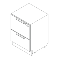
- Double Drawer:
- Product Height: 32 3/16" - 34 9/16"
- Minimum Cavity Height: 32 5/16" - 34 11/16"
- Width: 23 5/8"
- Depth: 22 15/32"
- Minimum Cavity Width: 23 5/8"
- Minimum Cavity Depth: 22 7/8"
- Drawer Open (incl. cab): 20 1/8"
- Single Drawer:
- Product Height: 16 1/32"
- Minimum Cavity Height: 16 5/32"
- Width: 23 7/16"
- Depth: 22 7/16"
- Minimum Cavity Width: 23 5/8"
- Minimum Cavity Depth: 22 7/8"
- Drawer Open (incl. cab): 20"
- Electrical: 120V AC 60Hz 12amp max.
- Lid Seal (P/N525878): 4.5 PSI - 6 PSI
- Exhaust Valve (P/N525415): 9-12 Volt DC (pulsed), 70 ± 5 Ohms
- Lid Seal Air Pump (P/N525430): 3-6 Volt DC (pulsed), 16 ± 2 Ohms
- Water Inlet Valves:
- Double (P/N525113): 15-20 Volt DC (pulsed), 70 ± 5 Ohms, 1.325 gal/min
- Single (P/N525842): 15-20 Volt DC (pulsed), 70 ± 5 Ohms, 1.325 gal/min
- Flood Switch (P/N525941): 24Volt DC Double Pole
- EMI Filter (P/N525934): 120 Volt AC
- Detergent Dispenser (P/N 525675): 15-20 Volt DC (pulsed), 70 ± 5 Ohms. Dispenses 0.18, 0.36, 0.54 ounces, and 0.18 ounces pre-rinse.
- Rinse Aid Dispenser: 12-18 Volt DC (pulsed), 70 ± 5 Ohms. Dispenses 0.013 gal, approx. 25 regular washes.
- Electronic P.C.B. (P/N525832P): 120 Volt AC inputs, 120 Volt AC, 40 Volt DC, 24 Volt DC outputs.
- Control Panel Std (P/N525192P): 24 Volt DC
- Control Panel Integrated (P/N525185P): 24 Volt DC
- Motor: 12-40 Volt DC 3 Phase, 42000 RPM
- Drain Wash: 2300-2850 RPM
- Stator (P/N525933): 2.5 ± 0.2 Ohms per winding
- Rotor (P/N525736): N/A
- Inlet Hose (P/N525937): 67 inches, 139.2 PSI
- Drain Hose (P/N525435, P/N525495): 78 13/16 inches from rear of cabinet. 98 1/2" bottom tub, 114 1/4" top tub.
- Temperature Sensor (Part of Heater Plate): 962 Ohms @ 68°F, 1000 Ohms @ 86°F, 1202 Ohms @ 140°F
- Heater Plate (P/N525814): 110 Volt AC
Usage Features
The DishDrawer features an electronic controller with two microcontrollers: one for motor control and output switching, and another for interface and console functions. The user interface includes a printed circuit board for front controls and a touch switch panel for internal controls. Integrated models use a Red center LED and Red LEDs on the touch switch panel to indicate faults, as they lack an LCD.
Diagnostic Modes:
- Temperature Display Mode: During a wash cycle, the current water temperature can be displayed on the LCD by initiating keylock (hold Keylock for 4 seconds) and then holding Start/Pause for 8 seconds.
- Rinse Aid / Tub-Open Beep Water Pressure Setup Mode: Entered by holding Program and Eco touch switches simultaneously for 5 seconds.
- Rinse Aid Setup: Adjusts rinse aid dispensed volume (1-5 levels) using the Program button. Setting is stored in EE memory.
- Tub-Open Beep Setup: Toggles the beep sequence when the tub is opened using the Keylock button.
- Water Pressure Set Up: Sets inlet water pressure to High (Standard) or Low (less than 50kPa/7.25 PSI) using the Start/Pause button.
- Dishwasher Diagnostics: Entered from Power Off mode by holding Keylock and Start/Pause simultaneously for 6 seconds. There are four levels of diagnostics, navigated by pressing Power.
- Display / Download Mode: Illuminates all LEDs (except Rinse program) and LCD segments (except keylock).
- Optical LED Download / Fault Display: Downloads EE data to a PC via the Rinse Program Red LED. Displays the last two fault codes (Current and Previous).
- Clearing Fault Logs: Press Keylock to move Current Fault to Previous Fault, then press Keylock again to clear Previous Fault.
- Show Off Mode: Initiates a shop show-off display and operation demonstration. Exited by removing mains power.
- Hardware Output Diagnostic Test Mode: Tests all hardware outputs and inputs. Displays current output in green (on) or red (off) on the touch switch panel and LCD. Outputs can be toggled using Keylock.
- Continuous Cycle Life Test Mode: Runs the dishwasher continuously in any wash cycle. Indicated by alternating green and orange backlight. Cycle count can be displayed by pausing during a continuous cycle.
Fault Codes: The dishwasher displays 10 F (fatal) faults and 10 U (user) faults. Fatal faults typically require service, while user faults are often blockages or installation errors. Faults are indicated on the LCD or by Red LEDs on integrated models. The last two faults are logged with 8 bytes of information for diagnosis. Faults can be cleared by pressing the Power button, but only if the fault is no longer present.
Maintenance Features
The DishDrawer is designed with several components that can be accessed and serviced.
Service Procedures:
- Drawer Front Removal: Involves locating and pulling out draw pins on either side of the tub, then easing the front down and forward from locating slots.
- Handle and LCD Display Removal: Requires removing the drawer front, then pulling handle tabs to release them. The LCD display is held by a spring tab and can be released with a small blade screwdriver.
- Drying Fan Removal: After removing the drawer front, slide the fan duct forward, disconnect wiring, and release securing tabs.
- Detergent Dispenser Removal: Remove the drawer front and handle, disconnect wiring, unclip the retainer flap and rinse aid LED, unclip the fill hose, and unscrew six T10 Torx screws.
- Electronic Controller Removal: Remove the drawer front and handle, pull the controller forward to clear the tub edge, disconnect wiring connectors, and then lift clear.
- Kick Strip Removal (Top and Lower): Top kick strip is removed by pulling it forward and tipping it up. Lower kick strip is unclipped with a flat blade screwdriver.
- Wiring Cover Removal: Unclip front legs and release three clips on the underside of the tub, then move it forward from the link assembly.
- Filter Plate Removal: Remove lower racks, drain filter assembly, and rotate the filter plate locknut anti-clockwise.
- Rotor Assembly Removal: Remove filter plate, then rotate the rotor locking ring anti-clockwise. The assembly is not serviceable.
- Tub Removal: Remove drawer front, wiring cover, fill hose, mains and chassis harness connectors, drain hose cuff, and wiring looms from the link assembly. Unhook the link assembly and slide the tub forward off the runners.
- Locking Ring, Element Plate, and Motor Assembly Removal: Remove drawer front, tub, filter plate, and rotor assembly. Disconnect wiring from heater plate and motor, and the rotor position sensor. Rotate the locking ring anti-clockwise while lifting the tab.
- Lid Assembly Removal: Remove tub assembly, disconnect lid plumbing, and release two locking tabs at the front of the lid.
- Lid Seal Replacement: Remove lid assembly, then grasp the seal in the middle and ease it away from the lid. The new seal is a push-in type and does not require sealant. Testing the gasket with an air gauge (pump to 6psi, pressure should not drop below 4.5psi over 60 seconds) is advisable.
- Slide Runner Replacement: Remove the tub, then remove two Philips head screws at the front of the slide runner. Tap the runner from underneath to free it.
- Front Trim Replacement: Break retaining clips with a blade screwdriver, then align clips on the new trim with chassis holes and push home.
- Sound Gasket Replacement: Pull the gasket out of the trim. To refit, feed ends into the trim slot, then push the middle section and roll with a coin.
- Link Assembly Removal: Remove tub, release clips on the side of the link assembly, and wedge out spigots in the hinge point.
- Air Pump Removal: Can be done by removing the tub assembly or lower kick strip. Disconnect air plumbing and wiring connector, then release from rubber mount.
- Exhaust Valve Removal: Can be done by removing the tub assembly or lower kick strip. Lift the valve to disengage from the chassis, disconnect air plumbing and wiring.
- Water Valve Removal: Remove lower tub, disconnect wiring to solenoids, inlet hose, and fill hoses.
- Flood Switch Removal: Remove lower tub, disconnect wiring, and release from chassis by squeezing pins.
- EMI Filter Removal: Remove lower tub, screw in rear access panel, and raise insulating cover.
- Tub Microswitch Removal: Can be done by removing the slide runner or lower kick strip. Disconnect wiring and release from retaining clips.
Safety Precautions:
- Electrical Safety: Disconnect mains power before servicing. If power is needed for diagnostics, turn it off when removing electrical components.
- Electrostatic Discharge (ESD): Use an anti-static strap when servicing electronic components.
- Good Working Practices: Maintain a tidy work area and clean the DishDrawer after service.
- Isolate Water Supply: Turn off the water connection tap before servicing.
- Water Leak Check: Perform a water leak check after service.
- Insulation Test: Megger test for insulation, shorting phase and neutral pins on the plug to protect electronics.
- Solvent and Excessive Heat Damage: Avoid damaging plastic surfaces with solvents or excessive heat.
- Sheet Metal Edges: Use gloves or protection when working around cut sheet metal edges.
- Diagnostics Warning: Some safety devices are bypassed in diagnostics mode. Do not run components unattended to prevent overheating, flooding, burnout, or water damage. Avoid turning on the element without water in the tub.