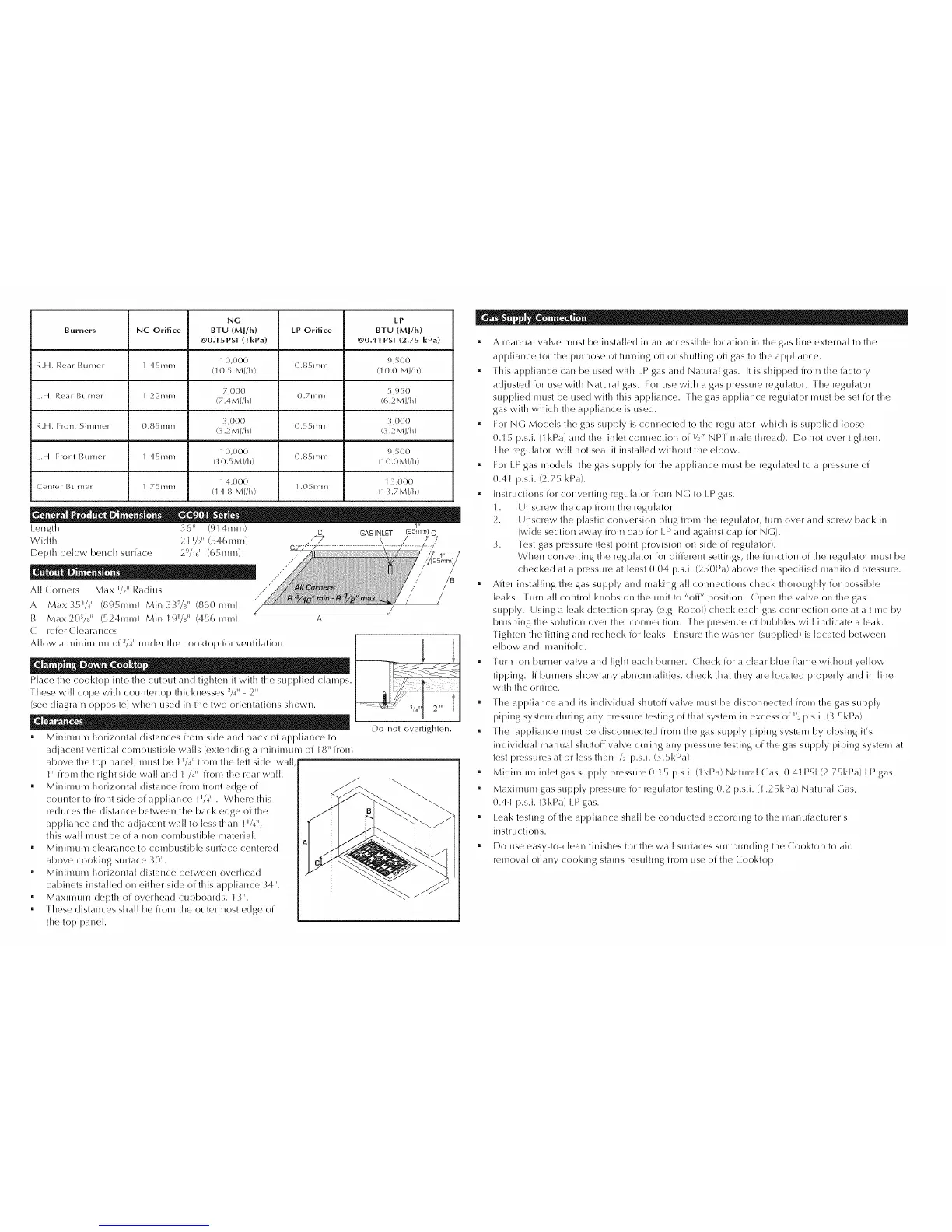
NG LP
Burners NG Orifice BTU (MJ/h) LP Orifice BTU (MJ/E)
@O.+15PSI (] kPa) @O.4+1 PSI (2.75 kPa)
JR.[ I. [',}ear Burner 1.45toni I 0,000 0.851_11_1 !),500
(I 0.5 Mj/h) (I 0.0 Mj/h)
I .I I. I',>ear Btllnel 1.22nlm 7,000 0.7me 5,950
(7.4M j/h) ff,.2Mjlh)
I',>.1 I. Fronl Sh11111c,I 0.8r;llln1 3,000 0 r r illn I 3,000
(3.2MWi9 (3.2 MWi9
I .I I. I IOlll l_tlfllOf 1,45111nl I 0,000 0,85111111 !),500
(l 0,', Ml/h) (l 0,0 Ml/h)
(2,nlcq [3tilnc,l 1.75mm I 4,000 1.05HI1_1 I 3,000
( t 4.8 Mj/h) (l 3.7Mj/h)
t ength g"o" (9 14me) 6ASINLTT s"
Width 21 _/2" (5461_Im)
DelJth below bench suriace 29/16I' (65me)
I D " 0
All COHIeFS Max _/2"Radius
A Max35W' (895mm) Min337/8 '' (860mm1
I:_ Max 2()s/d ' (524mm) Min I !)1/811 (486 I/ll/l) A
C rek'r (tearauces
Allow a minilllulll of 3/,€' under the cooktop ior ventilation.
Place the cooktop into tile CtltO/lt and tighten it with the sUf)l}lied clamps.
these witt cope with countertop thickuesses 3/+ 11 2 I1
(see diagram opposite) when used in the two orientations shown.
• Minimum horizontal distances i/om side aud back of appliance to
adjacent vertical combustible walls (extendiug a rniuil'nUl'n of t 8IIirom
above the top panel) must be t _/,_"i/om the left side watt
t" irom tile right side watt and l I/311 i/Om the rear watt.
• Miniimml horizontal distauce irom flout edge ot
cotillter to i]ollt side el apIJtiauce I l/311 . Where tiffs
reduces tile (Jistance between tite back edge of the
appliance alld the adjacent watt to tess !halt t _/_",
this watt i'qtlst be of a non combustible material.
" Mininlul'n clearance to combustible suriace centered
above cookiug suriace 3()".
" MhlilllUm horizontal distauce betweelt overhead
cabiltets installed oil either side of this apptiaitce ")4".
• Maximum depth of ow_rhead cupboards, t +}".
• these distallces shall be irom the outerrnost edge of
the top panel.
Do not overtighten.
• A Illauuat valve I'nUSt be iustatted in all accessible location ilt the gels tiue external to the
appliance ior the purpose of turning offer shutting ofigas to the apptiallce.
• this appliance cau be tised witil t P gas an(J Natural gas. It is shipped from tile iactory
a(Jjuste(J ior use with Natural gas. For use with a gels pressure regulator, the regulator
supplied must be used with this apptiailce, the gels api}tiance regulator mtlst be set ior the
gels with which tile appliance is used.
• For NG Models tite gas supply is conuected to tile regulator which is supplied loose
0.t 5 p.s.i. (I kPa) an(J the inlet coitile(::tioll oi rZ," NP t male thread). Do not over tighten.
the regulator wilt ltOt seat ii installed without tile elbow.
• l:or t P gels models tile gels supply ior the appliance i'iltlst be regulated to a pressure of
0.41 p.s.i. (2.75 kPa).
• tustructions ior convertiug regulator i]om NG to t P gels.
t . t_JltsCI'OWthe celI) iroll} the regulator.
2. t Jltsorew !lie plastic OOlWersioll plug 7roe !lie regtltator, tttrn over and screw back ill
(wide section away 1]'O1"_I cap iOl t P alld against cap iOl" N(-]).
"). lest gels pressure (test point provision oil side oi: regulator).
When COliVertillg the regulator ior diiierellt settiugs, tile itlllctioll Of tile regulator must be
checked at a pressure at least 0.04 p.s.i. (250Pa) above the speciiied mauiiotd pressure.
• After ills!ailing the gels supply and making all connections check thoroughly ior possible
leaks, turn all control kuobs oil the unit to "off _' position. Open the valve oil tile gas
supply. Using a leak detection spray (e.g. Rocot) check each gas connection one at a time by
brushing tile solution over tile connection, the presence of bubbles wilt indicate a leak.
lighten the it!ring alld recheck ior leaks. Ensure the washer (supplied) is located between
elbow alld maliiiotd.
• [ urn oil burner valve aii(J light each buruer. Check iora clear blue itame without yellow
tif)piug, ti burilers show any abnorrnalities, check that they are located properly and ill line
witil the oriiice.
• the apiJtiauce and its iudividuat shutoi] valve i'iltlst be discollllected irol'_l the gas supply
pilling system during auy press!ire testing of that system iu excess of w2p.s.i. (+L5kPa).
• the apptiauce must be disconnected irol'_l tile gas supply pipiug system by ctosiug it's
iudividuat inanuat shutoff valve during any ioressure testing of the gas supply piping system at
test pressures at or tess thau _/2 p.s.i. (3.SkPa).
• Mininlum inlet gas supply pressure 0. t 5 p.s.i. (t kPa) Natural (]as, 0.4t PSi (2.75kPa) t P gas.
" Maxiinurn gas supply pressure ior regul<dor testing 0.2 p.s.i. (t .25kPa) Natural Gas,
0.44 p.s.i. (3kPa)t P gas.
• t eak testing el thc, apiJtiance shall be conducted according to tile rnanuiacturer's
instructions.
• Do use easy to clean iinishes ior tile watt SLII'iacos StlHOtllldillg the Cooktop to aid
retrieval of any cooking stains resulting froth use of tile Cooktop.
 Loading...