Instruction Manual
D200099X012
249 Caged Sensors
April 2017
3
The unconnected end of the tube is sealed by a gasket and clamped rigidly to the torque tube arm, permitting the
protruding end of the shaft to twist and therefore transmit rotary motion. This allows the interior of the torque tube to
remain at atmospheric pressure, thus eliminating packing and the disadvantages of packing friction.
The displacer always exerts a downward force on one end of the displacer rod. The other end of the displacer rod rests
on the knife‐edge of the driver bearing. A keyed shaft on the bearing end of the displacer rod fits into a socket on the
outside of the welded end of the torque tube assembly.
A change in liquid level, interface level, or density/specific gravity buoys up the displacer by a force equal to the weight
of the liquid displaced. Corresponding vertical movement of the displacer results in angular movement of the displacer
rod around the knife edge. Since the torque tube assembly is a torsional spring which supports the displacer and
determines the amount of movement of the displacer rod for a given displacement change, it will twist a specific
amount for each increment of buoyancy change. This rotation is brought through the torque tube arm by the
protruding rotary shaft. A controller or transmitter attached to the end of the rotary shaft converts the rotary motion
into varying pneumatic or electric signals. Figure 4 shows how the controller or transmitter mounts on the torque tube
arm.
Unless otherwise noted, all NACE references are to NACE MR0175-2002.
Figure 4. Torque Tube Arm Exploded View Showing Controller or Transmitter Mounting
X1469
CONTROLLER OR TRANSMITTER
(DLC3010/DLC3020f
SHOWN)
RETAINING
FLANGE
POSITIONING
PLATE
GASKET
TORQUE
TUBE ARM
ROTARY SHAFT
OUTER
TUBE END
MOUNTING HOLES ACCEPT
FOUR STUDS OR CAP SCREWS
DEPENDING ON CONTROLLER OR
TRANSMITTER
HEX NUTS OR CAP
SCREWS DEPENDING ON
CONTROLLER OR TRANSMITTER
Type Number Description
249—CL125 or 250 cast iron cage with screwed or flanged connections.
249B—CL150, 300, or 600 steel cage with screwed or flanged connections.
249BF—CL150, 300, or 600 cast steel or stainless steel cage with flanged connections only. Available from Emerson
Automation Solutions in Europe only.
249C—CL150, 300, or 600 stainless steel cage with screwed or flanged connections.
249K—CL900 or 1500 steel cage with flanged connections only.
249L—CL2500 steel cage with flanged connections only.
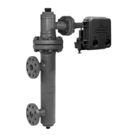
The cage head on all of the 249 constructions may be rotated to any of the eight alternate positions shown in figure 7.
Connection sizes are either NPS 1‐1/2 or 2.