Instruction Manual
D101402X012
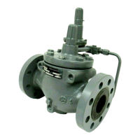
3660 and 3661 Positioners
September 2015
22
Install the connectors and hardware between the 3660 or 3661 positioner and the actuator.
1. Before assembling the pipe nipple, pipe tee, pipe bushings, actuator piping, and connector body, apply sealant to
all threads. Sealant is provided with the diagnostic connectors and hardware.
2. Turn the pipe tee to position the connector body and body protector for easy access when doing the diagnostic
testing.
Vent Connection
3660 and 3661 positioners are equipped with a 1/4 NPT vent connection in the cover.
Electrical Connections for 3661 Positioners
WARNING
For intrinsically safe installations, refer to the loop schematics shown in figures 27 and 28, factory drawings, or to
instructions provided by the barrier manufacturer for proper wiring and installation.
Select wiring and/or cable glands that are rated for the environment of use (such as hazardous area, ingress protection, and
temperature). Failure to use properly rated wiring and/or cable glands can result in personal injury or property damage
from fire or explosion.
Wiring connections must be in accordance with local, regional, and national codes for any given hazardous area approval.
Failure to follow the local, regional, and national codes could result in personal injury or property damage from fire or
explosion.
Refer to figures 17 and 18 when making electrical connections. Use the 1/2 NPT conduit connection for installation of
field wiring. Run the input wires through the conduit, and connect the positive wire from the control device to the
positioner + terminal and the negative wire from the control device to the positioner - terminal. Do not over tighten
the terminal screws. The maximum torque is 0.45 NSm (4 lbfSin.).
Figure 17. Equivalent Circuit
21B2335‐D
A6012
5.6V
5.6V
5.6V
60 Ohms
60 Ohms
4 - 20 mA
+
−
Figure 18. Typical Field‐Wiring Diagram
+
-
+
-
-+
1
CONTROL
DEVICE
POSITIONER
HOUSING
TERMINAL
BLOCK
FIELD WIRING
EARTH
GROUND
NOTE:
1 FOR TROUBLESHOOTING OR MONITORING OPERATION,
AN INDICATING DEVICE CAN BE A VOLTMETER ACROSS
A 250 OHM RESISTOR OR A CURRENT METER.
A3875