Instruction Manual
D101402X012
3660 and 3661 Positioners
September 2015
36
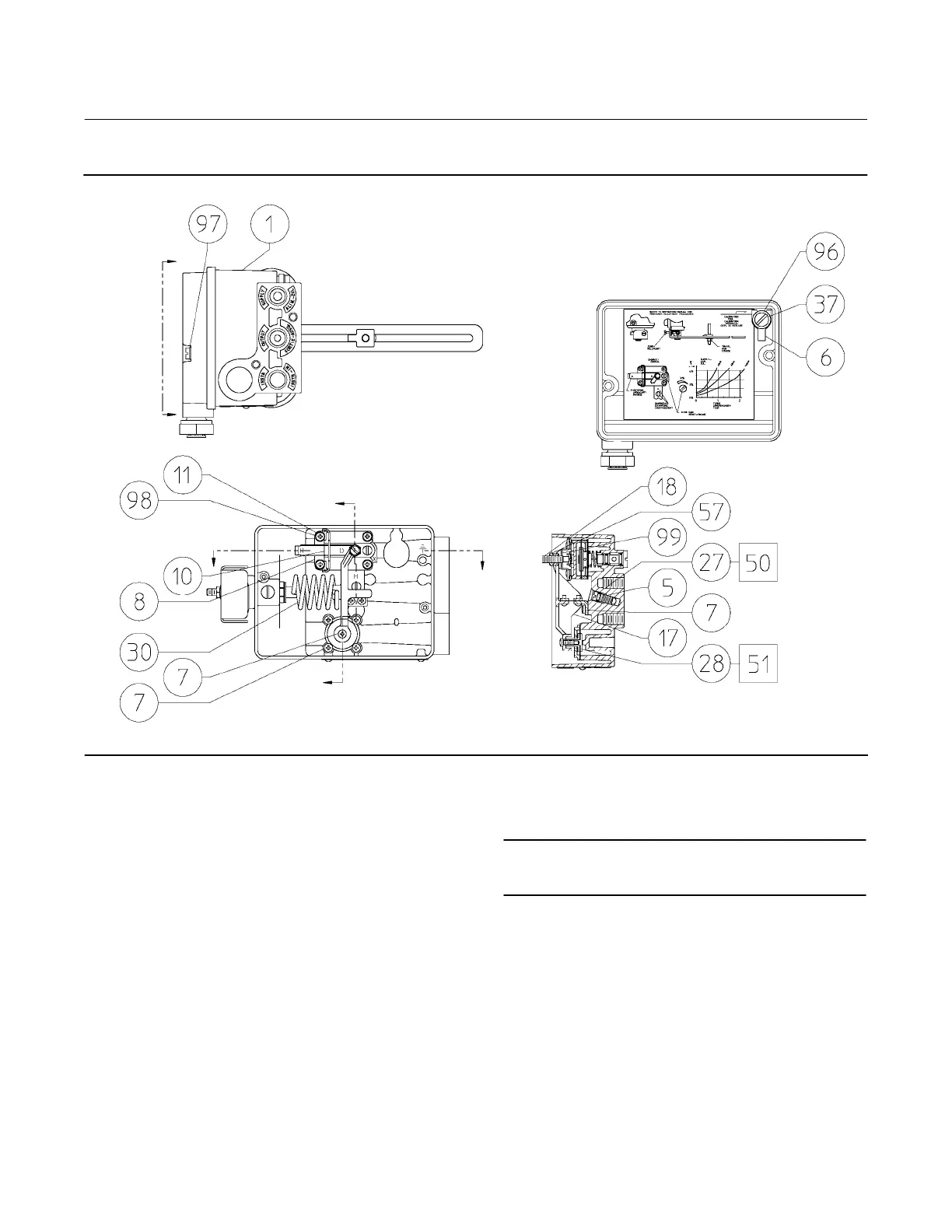
Figure 24. Fisher 3660 Positioner Assembly (continued)
A
A
B
B
C
C
VIEW A‐A
WITHOUT COVER
SECTION B‐B
51B3944‐F
Key Description Part Number
38* Output gauge (optional)
Dual scale
0 to 2 Kg/cm
2/
0 to 30 psig 11B4036X042
0 to 11 Kg/cm
2/
0 to 160 psig 11B4036X062
Triple scale
0 to 2 bar/0 to 0.2 MPa/0 to 30 psig 11B4036X012
0 to 11 bar/0 to 1.1 MPa/0 to 160 psig 11B4036X032
39* Instrument gauge (optional for 3660 Only)
Dual Scale
0 to 2 Kg/cm
2/
0 to 30 psig 11B4036X042
0 to 4 Kg/cm
2/
0 to 60 psig 11B4036X052
Triple scale
0 to 2 bar/0 to 0.2 MPa/0 to 30 psig 11B4036X012
0 to 4 bar/0 to 0.4 MPa/0 to 60 psig 11B4036X022
40 Anti‐seize sealant
(not furnished with positioner)
Key Description
Note
Keys 41 through 49 and key 79 apply to 3660 with bypass valve only.
Refer to figure 23.
41 Bypass body assembly, aluminum
42 Bypass lever assembly, plastic
43* O‐ring, EPDM
44* O‐ring, EPDM
45* O‐ring, (2 req'd)
46 Retaining ring, stainless steel
47 Cheese head screw, (2 req'd)
48 Lubricant, silicone sealant
(not furnished with positioner)
49* O‐ring, EPDM (3 req'd)
50 Lubricant, silicone sealant
(not furnished with positioner)
*Recommended spare parts
 Loading...


