www.Fisher.com
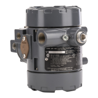
Fisherr 546 Electro‐Pneumatic Transducer
Contents
Introduction 1.................................
Scope of Manual 1.............................
Description 3.................................
Specifications 4...............................
Educational Services 4.........................
Installation 5..................................
Mounting 5..................................
Pressure Connections 5........................
Diagnostic Connections 6......................
Electrical Connections 6........................
Operating Information 7.........................
Adjustments 8................................
Calibration 8.................................
Equipment Required 8......................
Calibration Procedure 9.....................
Recalibration 10...........................
Changing Output Pressure Range 10.............
Reversing the Action 10........................
Split Range Operation 11.......................
Principle of Operation 11........................
Maintenance 13................................
Relay Removal and Replacement 14..............
Replacing the Feedback Bellows Assembly 14......
Troubleshooting 14............................
Electrical 14..............................
Pneumatic 15.............................
Alignment 15.................................
Span Adjustment 15.......................
Torque Motor Frame 16....................
Armature Travel Stop 16....................
Coil 16...................................
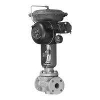
Figure 1. Fisher 546 Electro‐Pneumatic Transducer
Mounted on a 657 Pneumatic Diaphragm Actuator
W2115
546
FILTER
REGULATOR
Parts Ordering 16...............................
Parts List 17...................................
Repair Kits 17.................................
Transducers 17...............................
Torque Motor 18..............................
Mounting Parts 20.............................
Diagnostic Connections 22.....................
Introduction
Scope of Manual
This instruction manual provides installation, operation, maintenance, and parts ordering information for Fisher 546
transducers and the 82 relay. Refer to separate manuals for instructions covering equipment used with the transducer.
Do not install, operate or maintain a 546 transducer without being fully trained and qualified in valve, actuator and
accessory installation, operation and maintenance. To avoid personal injury or property damage it is important to
carefully read, understand, and follow all of the contents of this manual, including all safety cautions and warnings. If
you have any questions about these instructions, contact your Emerson Process Management sales office before
proceeding.
Instruction Manual
D200108X012
546 Transducer
March 2015


