Type 655 and 655R
2
Table 1. Specifications
Actuator Sizes and Maximum Casing Pressures
ACTUATOR
MAXIMUM CASING PRESSURE
SIZE
Psig Bar
3A, 4A 250 17.2
3B, 4B 175 12.1
32, 42 100 6.9
33, 43 65 4.5
34, 44 45 3.1
35, 45 30 2.1
36, 46 15 1.0
Actuator Pressure Setting Ranges
See table 2
Actuator Yoke Boss and Valve Stem Connection
Diameters
Sizes 3A through 36: 2-1/8 inch (54 mm) yoke
boss with 3/8 inch (9.5 mm) stem connection
Sizes 4A through 46: 2-13/16 inch (71 mm) yoke
boss with 1/2 inch (12.7 mm) stem connection
Maximum Travel
Sizes 3A and 4A: 7/16 inch (11 mm) plus 1/8 inch
(3 mm) for seating
All Other Sizes: 3/4 inch (19 mm) plus 1/8 inch (3
mm) for seating
Effective Diaphragm Area
See table 3
Spring Rate
See key 6 in the parts list section
Temperature Capabilities
–20 to 180F (–29 to 82 C) with standard dia-
phragm material. For the fluid and temperature ca-
pabilities of nonstandard diaphragm materials, con-
sult your Fisher Controls sales office or sales
representative
Casing Pressure Connections
1/2 inch NPT female
Approximate Weights
ACTUATOR
APPROXIMATE WEIGHT
SIZE
Lb Kg
3A, 3B, 32, 33 45 20
34, 35, 36 50 23
4A, 4B, 42, 43 65 29
44, 45, 46 75 34
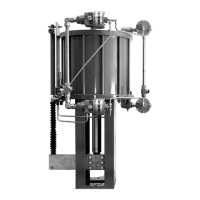
Description
Type 655 and 655R actuators (figure 1) are pressure-
actuated, spring-and-diaphragm actuators used in
conjunction with various valves to provide control for a
wide variety of pressure regulation applications. Type
655 actuators are used for pressure-reducing service
when mounted on push-down-to-close valves such as
the Design ED, EK, and ET valves. Type 655R actua-
tors are used for pressure-relief service when mounted
on push-down-to-open valves such as the Design
EDR, EKR, and ETR valves. Both types are self-oper-
ated and direct-acting; that is, increasing pressure in
the diaphragm casing forces the actuator stem down-
ward, and decreasing the pressure allows the actuator
spring to lift the actuator stem upward.
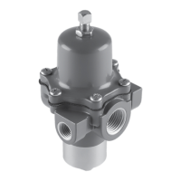
Specifications
Specifications for the Type 655 and 655R actuators
are shown in table 1. Information for a specific actua-
tor is also found on the nameplate (figure 2) of that
actuator.
Installation
WARNING
To avoid personal injury or property
damage caused by bursting of pressure-
retaining parts, be certain the service
conditions do not exceed the casing
pressure limits listed in table 1. Use
pressure-limiting or pressure-relieving
devices to prevent service conditions
from exceeding these limits.
Type 655 and 655R actuators are normally shipped
mounted on a valve. Refer to the appropriate valve
instruction manual when installing the valve in the
pipeline. If the actuator is shipped separately or if it is
necessary to mount the actuator on the valve, perform
the procedures described in the
Actuator Mounting
portion of this section.
Before installing the actuator, inspect it for any dam-
age. Also, keep any adjacent piping clean and free of
pipe scale or other debris that could possibly disrupt
service. It is recommended that a strainer be installed