912 Series
R
2
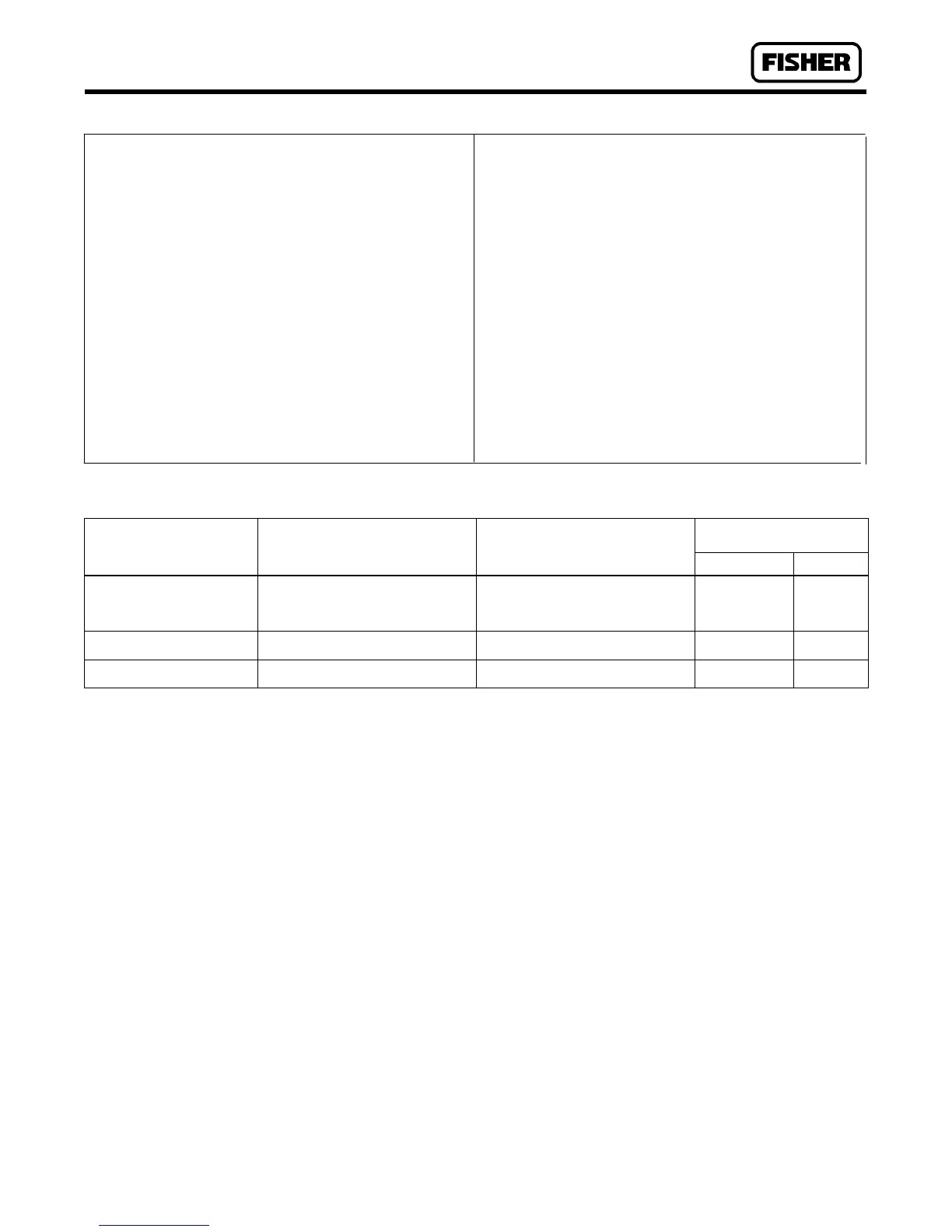
Table 1. Specifications
AVAILABLE See table 2
CONFIGURA TIONS
BODY SIZES AND END Inlet: 1/4-inch NPT screwed
CONNECTION STYLES Outlet: J 1/4 or J 3/8-inch NPT
screwed
MAXIMUM 250 psig (17 bar)
ALLOW ABLE INLET
PRESSURE
OUTLET PRESSURE See table 2
RANGES
MAXIMUM Maximum Emergency Outlet
ALLOW ABLE OUTLET Pressure: 20 psig (1.4 bar)
PRESSURE Maximum Recommended Outlet
Pressure to Avoid Internal Part
Damage: 3 psi (0.21 bar, differ-
ential) above outlet pressure setting
INTERNAL RELIEF Approximate Internal Relief Valve
PERFORMANCE Start-to-Discharge Point: See
table 2
Capacity: Adequate only for relieving
minor buildup situations such as are
caused by chips or dirt blocking the
seat partly open; for major malfunctions,
external relief is required according to
the ‘‘Installation’’ section.
MA TERIAL -20 to 160_F (-29 to 71_C)
TEMPERA TURE
CAP ABILITIES
PRESSURE Internal
REGISTRA TION
APPROXIMA TE 1.3 pounds (0.6 kg)
WEIGHT
Table 2. Outlet Pressure Range Data
APPROXIMA TE POINT ABOVE
OUTLET PRESSURE SETTING
CONTROL SPRING
SELECTION
AT WHICH INTERNAL RELIEF
ST ARTS T O DISCHARGE
Part Number Color Code
Type 912 without handwheel
3 to 7 inches w.c. (7 to 17 mbar)
5 to 10 inches w.c. (12 to 25 mbar)
9.25 to 13 inches w.c. (23 to 32 mbar)
12 to 24 inches w.c. (30 to 60 mbar)
5 to 21 inches w.c. (12 to 52 mbar)
8 to 30 inches w.c. (20 to 75 mbar)
16 to 39 inches w.c. (40 to 97 mbar)
17 inches w.c. to 3 psig (42 to 210 mbar)
1B7843 27222
1B7844 27222
1L5079 37022
1B7845 27222
Red
Orange
Cadmium
Blue
Type 912H without handwheel
1 to 2.5 psig (69 to 172 mbar)
2.7 to 5 psig (186 to 340 mbar)
0.7 to 6.8 psig (0.05 to 0.47 bar)
3.8 to 12.5 psig (0.26 to 0.86 bar)
1B7846 27222
1B7847 27222
Yellow
Green
912 Series with handwheel
0 to 1 psig (0 to 69 mbar)
0 to 5 psig (0 to 340 mbar)
0 to 3 psig (0 to 210 mbar)
0 to 12.5 psig (0 to 0.86 bar)
1C5804 27222
1C5805 27012
Black
Brown
area. The vent opening on the regulator or the
opening on the remote vent pipe (if one is used)
should be pointed down to minimize clogging
from collected moisture, corrosive chemicals,
or other foreign material. Overpressuring the
downstream system (and risk of explosion)
could result from a clogged vent.
Overpressuring any portion of a regulator or
associated equipment may cause leakage, part
damage, or personal injury due to bursting of
pressure-containing parts or explosion of accu-
mulated gas.
Like most regulators, the 912 Series regulators have an out-
let pressure rating lower than the inlet pressure rating.
Downstream protection is required if the actual inlet pres-
sure can exceed the regulator outlet pressure rating or the
pressure rating of any downstream equipment.
Regulator operation within ratings does not preclude the
possibility of damage from external sources or from debris
in the lines. A regulator should be inspected for damage pe-
riodically and after any overpressure condition.
Ensure that the regulator is undamaged and contains no
foreign material. Install the regulator so that flow through it
leaves the outlet port (marked on the body). The regulator
may be installed in any position, however, the spring case
vent should be pointed down. Spring case/vent orientation
can be changed by rotating the spring case with respect to
the body.
For an indoor installation, if the regulator controls a gas that
is flammable or otherwise hazardous, a spring case with the
optional tapped vent should be used so that the exhaust can
be piped away. Provide protection on a remote vent by
installing a screened vent cap into the remote end of the
vent pipe. The vent should be pointed down.
Apply a good grade of pipe compound to the pipe threads
before making the connections. Install piping into the
1/4-inch NPT inlet connection and the 1/4-inch or 3/8-inch
NPT outlet connection.

 Loading...


