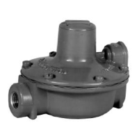
912 Series
3
Each regulator is factory-set for the pressure setting speci-
fied on the order. If no setting was specified, the outlet pres-
sure is factory-set at the mid-range of the control spring.
The procedure for adjusting the output pressure is given in
the ‘‘Startup’’ section.
ST ARTUP
Key numbers are referenced in figure 2.
With installation completed and downstream equipment
properly adjusted, slowly open the upstream and down-
stream shutoff valves while monitoring the regulator output
pressure.
WARNING
For the 912 Series constructions with no drive
screw in the spring case, never adjust the con-
trol spring to produce an outlet pressure higher
than the outlet pressure range for that particular
spring. Doing so could overpressure the system
and cause personal injury or equipment dam-
age. If the desired outlet pressure is not within
the range of the control spring, install a spring of
the proper range according to the ‘‘Mainte-
nance’’ section.
If outlet pressure adjustment is necessary, monitor the out-
let pressure with a gauge while performing the following
procedure:
1. For units without a handwheel, unscrew the closing cap
(key 3) and insert a screwdriver blade into the adjusting
screw (key 4).
2. Slowly turn the adjusting screw or handwheel clockwise
to increase or counterclockwise to decrease the output
pressure setting.
3. With the output pressure adjusted to the desired value,
replace the closing cap on units without a handwheel.
SHUTDOWN
Close the nearest upstream shutoff valve, then close the
nearest downstream shutoff valve, and vent pressure from
the outlet of the regulator.
MAINTENANCE
Regulator parts are subject to normal wear and must be in-
spected and replaced as necessary. The frequency of in-
spection and replacement of parts depends on the severity
of service conditions or the requirements of local, state, and
federal rules and regulations.
WARNING
To avoid personal injury or equipment damage,
do not attempt any maintenance or disassembly
without first isolating the regulator from system
pressure and relieving all internal pressure from
the regulator.
This procedure is to be performed if changing the control
spring for one of a different range, or for inspecting, clean-
ing, or replacing any other parts. Key numbers are refer-
enced in figure 2.
Note
If sufficient clearance exists, the regulator body
(key 1) can remain in the line during spring re-
placement or other maintenance procedures.
Control Spring Replacement
On units without the handwheel, unscrew the closing cap
(key 3) and turn the adjusting screw out of the spring case.
Lift out the control spring (key 5).
On units with a handwheel, turn the handwheel counter-
clockwise until the tension is relieved from the control
spring. Unscrew the nut at the base of the handwheel and
lift the handwheel off the spring case. Lift out the adjusting
screw and the control spring.
Replace the control spring and complete the assembly by
replacing the adjusting screw and the closing cap or hand-
wheel. Adjust the spring tension as described in the ‘‘Start-
up’’ section.
Diaphragm and Relief Valve
Replacement
Remove cap screws (key 14) and separate the spring case
from the valve body. Remove the control spring (key 5) and
the diaphragm (key 15) along with the diaphragm head (key
10), the relief valve seat (key 9) and the relief valve spring
(key 6). Separate these parts by removing the pin (key 8)
and the spring seat (key 7). Remove the disk holder assem-
bly (key 11) by removing two screws (key 13).

 Loading...