912 Series
R
4
To re-assemble the regulator, first assemble the relief valve
spring assembly, then replace the relief valve spring assem-
bly, the disk holder assembly, the diaphragm, the dia-
phragm head, and fit the spring case to the body. Install and
tighten cap screws (key 14) in a criss-cross manner. Adjust
the control spring tension as described in the ‘‘Startup’’ sec-
tion.
PARTS ORDERING
When corresponding with the Fisher representative about
this regulator, include the type number, date of manufac-
ture, and all other pertinent information from the labels.
Specify the eleven-character part number when ordering
new parts from the following parts list.
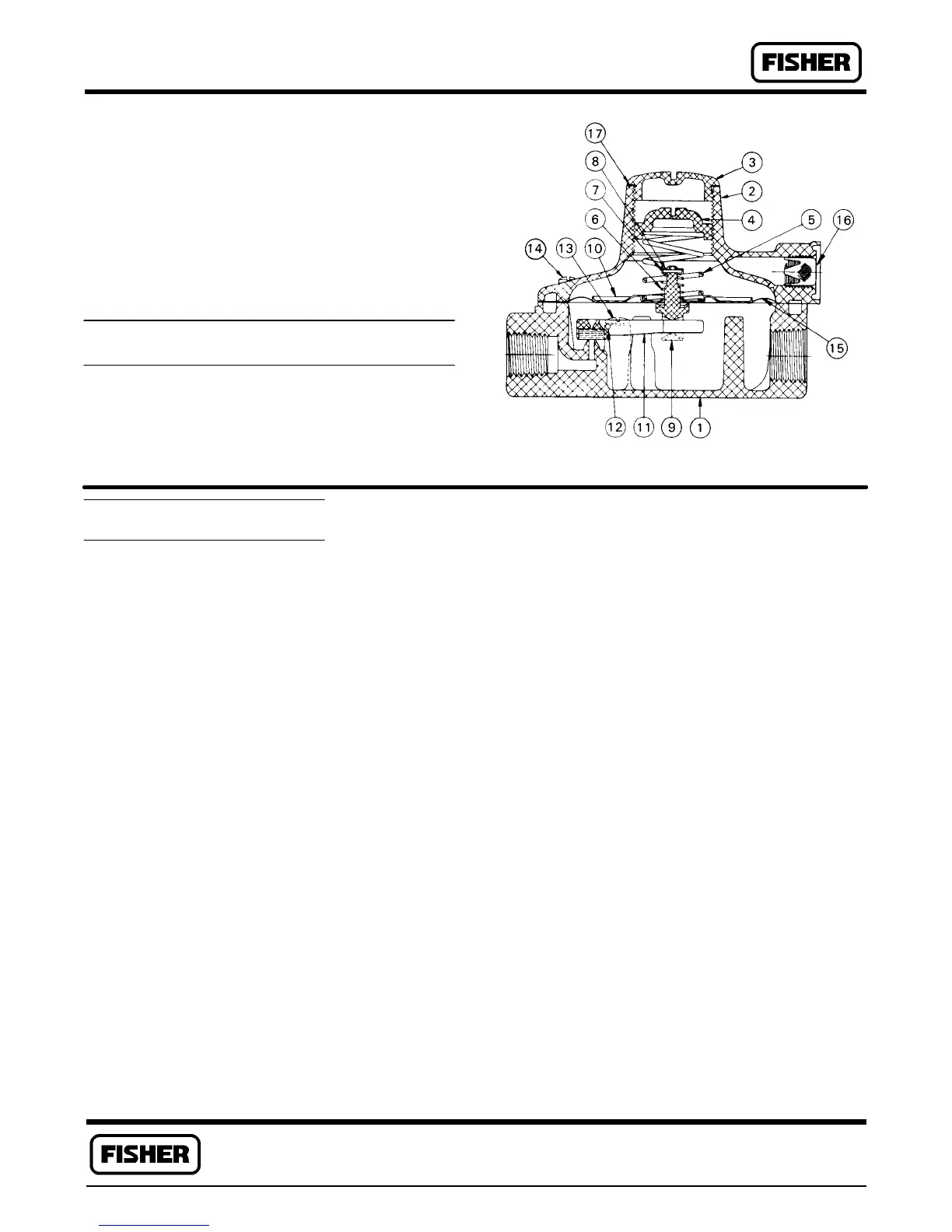
Figure 2. 912 Series Pressure Regulator Assembly
BD4632-H
Key Description Part Number
14 Machine Screw, steel pl
(6 req’d) 1B7839 28982
15 Diaphragm, rubber 1B7837 02012
16 Vent Screen,
Monel 0W0863 43062
17* Closing Cap Gasket, asbestos (use
with tapped vent only) 1E7652 04022
18 Closing Spring, SST, 912 Series
w/handwheel, only 1E3020 37022
19 Spacer Ring, brass, 912 Series
w/handwheel, only 1C5807 14012
20 Lockwheel, brass, 912 Series
w/handwheel, only 1C2346 14012
22 Warning Label
(not shown) 1P4879 06032
23 Spring Range Label (not shown)
1 to 2.5 psi (69 to
172 mbar) T10800 06992
2.7 to 5 psi (186 to
340 mbar) T10801 06992
0 to 1 psi (0 to
69 mbar) T10802 06992
0 to 5 psi (0 to
340 mbar) T10803 06992
25 Spring Seat, brass, 912 Series
w/handwheel 1C2345 14012
PARTS LIST
Key Description Part Number
1 Body, zinc
1/4 x 1/4-inch NPT
0.073 inch (1.8 mm)
port dia 3D3771 44042
1/4 x 3/8-inch NPT
0.073 inch (1.8 mm)
port dia 3B7824 44042
2 Spring Case, zinc
For use with control springs
1B7847 27222 (complete with drive
screw)
Untapped 1B7840 T00012
1/8-inch NPT tapped
vent T10895 T00012
For all other constructions
Untapped 3E2944 44042
1/8-inch NPT tapped
vent 1E2955 44042
3 Closing Cap
912 Series w/handwheel,
brass 1C2344 14012
All others, plastic T10276 06992
4 Adjusting Screw
912 Series w/handwheel, zinc
& steel 1B7992 000A2
All others, plastic T10277 06992
Key Description Part Number
5 Regulator Spring, steel pl.
9.25 to 13 inch w.c. (23 to 32 mbar),
cad. 1L5079 37022
3 to 7 inch w.c. (7 to 17 mbar),
red 1B7843 27222
5 to 10 inch w.c. (12 to 25 mbar),
orange 1B7844 27222
10 inch w.c. to 1 psi (25 to 69 mbar),
blue 1B7845 27222
0.5 to 2.7 psig (35 to 186 mbar),
yellow 1B7846 27222
0 to 1 psig (0 to 69 mbar),
black 1C5804 27222
0 to 5 psig (0 to 340 mbar),
brown 1C5805 27012
6 Relief Valve Spring,
steel pl 1B7848 27012
7 Spring Seat, steel pl 1B7834 25072
8 Pin, SST 1B7835 35032
9 Relief Valve Ass’y,
brass/zinc 1C3650 X0012
10 Diaphragm Plate, steel
Zn pl 1B7838 24132
11 Disk Holder Ass’y,
zinc/nitrile 1E3003 000A2
12 Fulcrum Rod, SST 0U0914 35032
13 Machine Screw, steel pl
(2 req’d) 1A3461 28982
*Recommended spare part.
Fisher Controls
For information, contact Fisher Controls:
Marshalltown, Iowa 50158 USA Sao Paulo 05424 Brazil
Cernay 68700 France Singapore 0512
While this information is presented in good faith and believed to be accurate,
Fisher Controls does not guarantee satisfactory results from reliance upon such
information. Nothing contained herein is to be construed as a warranty or guar-
antee, express or implied, regarding the performance, merchantability , fitness
or any other matter with respect to the products, nor as a recommendation to
use any product or process in conflict with any patent. Fisher Controls reserves
the right, without notice, to alter or improve the designs or specifications of the
products described herein.
R

 Loading...


