Instruction Manual
D101640X012
CV500 Valve
June 2017
3
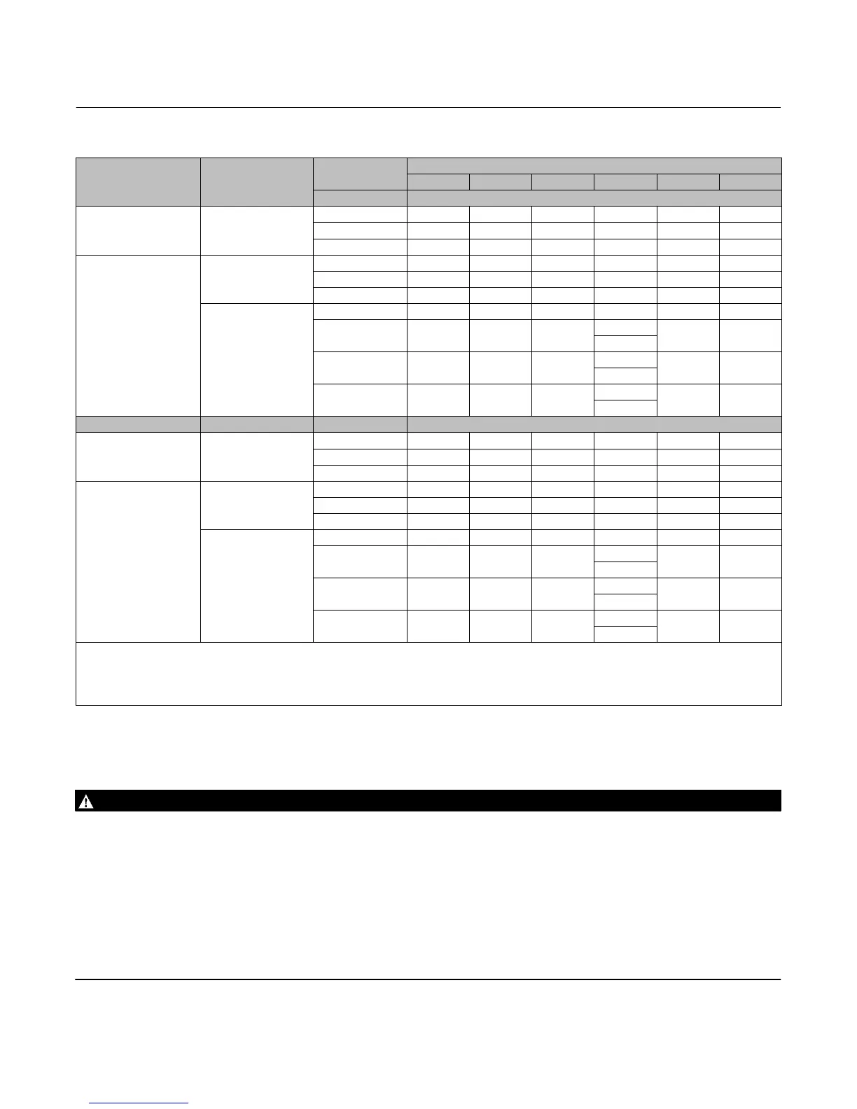
Table 2. Maximum Allowable Shutoff Pressure Drops
(3)
VALVE BODY MATERIAL BEARING MATERIAL
TEMPERATURE
VALVE SIZE, NPS
3 4 6 8 10 12
_C Bar
WCC steel
S44004
(440C SST)
-29 to 149 41.4 41.4 41.4 24.1 24.1 27.6
149 to 204 41.4 41.4 41.4 23.8 24.1 27.6
204 to 316 41.4 41.4 41.4 23.1 24.1 27.6
WCC steel, EN 1.0619
steel, CF8M (316 SST),
EN 1.4581 SST, or
CF3M
(4)
(316L SST)
R30006
(Alloy 6)
-46
(1)
to 204 41.4 41.4 20.7 15.1 24.1 27.6
204 to 260 41.4 41.4 20.7 15.1 24.1 27.6
260 to 316 41.4 41.4 20.7 15.1 24.1 27.6
PTFE/composition‐
lined S31603
(2)(4)
(316L SST)
-46
(1)
to 93 41.4 41.4 41.4 24.1 31 34.5
93 to 149 41.4 41.4 41.4
24.1
(5)
31 34.5
23.1
(6)
149 to 204 41.4 41.4 41.4
23.8
(5)
31 34.5
22.1
(6)
204 to 260
(2)
41.4 41.4 41.4
23.4
(5)
31 34.5
21.7
(6)
_F Psi
WCC steel
S44004
(440C SST)
-20 to 300 600 600 600 350 350 400
300 to 400 600 600 600 345 350 400
400 to 600 600 600 600 335 350 400
WCC steel, EN 1.0619
steel, CF8M (316 SST),
EN 1.4581 SST, or
CF3M
(4)
(316L SST)
R30006
(Alloy 6)
-50
(1)
to 400 600 600 300 220 350 400
400 to 500 600 600 300 220 350 400
500 to 600 600 600 300 220 350 400
PTFE/composition‐
lined S31603
(2)(4)
(316L SST)
-50
(1)
to 200 600 600 600 350 450 500
200 to 300 600 600 600
350
(5)
450 500
335
(6)
300 to 400 600 600 600
345
(5)
450 500
320
(6)
400 to 500
(2)
600 600 600
340
(5)
450 500
315
(6)
1. -29_C (-20_F) for WCC steel valve body material.
2. For hot water or steam service, limit maximum temperature to 260_C (500_F).
3. The pressure or temperature limits in this table or in any applicable code limitation, should not be exceeded.
4. Standard Fisher material offerings in Europe only.
5. S17400 (17‐4PH SST) shaft only.
6. S20910 stainless steel shaft only. Pressure drops appropriate for both shaft materials.
Installation
WARNING
Always wear protective gloves, clothing, and eyewear when performing any installation operations to avoid personal
injury.
Personal injury or equipment damage caused by sudden release of pressure can result if the valve assembly is installed
where service conditions could exceed the pressure drop limits given in table 2 or the valve rating. To avoid such injury or
property damage, provide a relief valve for overpressure protection as required by government or accepted industry codes
and good engineering practices.
Check with your process or safety engineer for any additional measures that must be taken to protect against process
media.
If installing into an existing application, also refer to the WARNING at the beginning of the Maintenance section in this
instruction manual.


 To Next Page