EasyManua.ls Logo

Fisher D4 User Manual

Fisher D4
20 pages
To Next Page IconTo Next Page
Page #1 background imageLoading...
Page #1 background image
www.Fisher.com
Fisherr D4 Control Valve Assembly
Contents
Introduction 1.................................
Scope of Manual 1.............................
Description 1.................................
Specifications 2...............................
Educational Services 2.........................
Installation 4..................................
Spring Adjustment 5............................
Maintenance 6.................................
Valve Plug and Seat Ring 6......................
Valve Packing 8...............................
Actuator 10..................................
Parts Ordering 13...............................
Repair Kits 14..................................
Parts List 14...................................
Appendix A 17.................................
Figure 1. Fisher D4 Control Valve
W8531
Introduction
Scope of Manual
This instruction manual provides installation, maintenance, and parts information for the Fisher D4 control valve.
Do not install, operate, or maintain a D4 control valve without being fully trained and qualified in valve, actuator, and
accessory installation, operation, and maintenance. To avoid personal injury or property damage, it is important to
carefully read, understand, and follow all the contents of this manual, including all safety cautions and warnings. If you
have any questions about these instructions, contact your Emerson Process Management sales office
before
proceeding.
Description
The D4 control valve is a compact, rugged valve designed primarily for high‐pressure throttling applications. This valve
is ideal for use on pressure and flow control applications within the oil and gas production industry. The D4 valve also
makes an excellent dump valve for high‐pressure separators and scrubbers.
The D4 control valve meets the metallurgical requirements of NACE MR0175/ISO 15156 without environmental limits
for temperatures below 135_C (275_F). If the temperature is above 135_C (275_F), the N07718 Belleville washers will
impose some limits, as shown in table 3.
Instruction Manual
D103042X012
D4 Valve
July 2015
Question and Answer IconNeed help?

Do you have a question about the Fisher D4 and is the answer not in the manual?

Fisher D4 Specifications

General IconGeneral
Enclosure RatingNEMA 4X, IP66
Input Signal4-20 mA
Temperature Limits-40 to 85°C (-40 to 185°F)
Input Voltage18-30 VDC
Communication ProtocolHART

Summary

Introduction

Scope of Manual

Defines the scope and purpose of the instruction manual for the Fisher D4 control valve.

Description

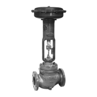
Provides a general overview of the Fisher D4 control valve's design and application.

Specifications

Maximum Inlet Pressures and Temperatures

Specifies the maximum allowable inlet pressures and temperatures for the D4 valve.

Maximum Pressure Drops

Details the maximum permissible pressure drops for the D4 control valve under various conditions.

Material Temperature Capabilities

Outlines the temperature limits for actuator and valve body assemblies.

Shutoff Classification

Indicates the valve's shutoff performance rating according to industry standards.

Actuator Casing Pressure

Specifies the maximum operating pressure for the actuator casing.

Educational Services

Installation

Spring Adjustment

Spring-to-Close

Step-by-step guide for adjusting the spring compression in a spring-to-close actuator.

Spring-to-Open

Step-by-step guide for adjusting the spring compression in a spring-to-open actuator.

Maintenance

Valve Plug and Seat Ring

Covers inspection and maintenance of the valve plug and seat ring components.

Valve Plug and Seat Ring Disassembly

Detailed steps for disassembling the valve plug and seat ring assembly.

Valve Plug and Seat Ring Assembly

Instructions for reassembling the valve plug and seat ring components.

Valve Packing

Information and procedures for maintaining the valve stem packing.

Valve Packing Disassembly

Steps to disassemble the valve packing for inspection or replacement.

Valve Packing Assembly

Instructions for assembling the valve packing components.

Actuator (Spring-to-Close)

Disassembly

Steps to disassemble the spring-to-close actuator assembly.

Assembly

Steps for assembling the spring-to-close actuator components.

Actuator (Spring-to-Open)

Disassembly

Steps to disassemble the spring-to-open actuator assembly.

Assembly

Steps for assembling the spring-to-open actuator components.

Parts Ordering

Repair Kits

Parts List

Appendix A

Valve Packing

Specific instructions for valve packing for models with serial numbers less than 18679262.

Valve Packing Disassembly

Steps to disassemble valve packing for older models (serial numbers < 18679262).

Valve Packing Assembly

Steps to assemble valve packing for older models (serial numbers < 18679262).

Related product manuals