Do you have a question about the Fisher 8580 and is the answer not in the manual?
Defines the scope of this instruction manual, covering installation, maintenance, and parts for the Fisher 8580 valve.
Details the Fisher 8580 rotary valve's throttling performance, linear flow characteristic, cycle life, and double-offset disk design.
Instructions for maintaining and adjusting valve packing to prevent leakage and ensure proper function.
Detailed steps for removing and installing new packing components, including safety precautions.
Procedure for replacing the seal ring assembly when the valve is not shutting off properly.
Steps for disassembling and replacing the valve disk, shafts, or bearings for proper functionality.
Guidelines for mounting and adjusting the actuator onto the valve body, referencing actuator instruction manuals.
Details available retrofit and repair kits for the ENVIRO-SEAL packing system, including PTFE and graphite options.
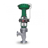
The Fisher™ 8580 Rotary Valve is a control device designed for throttling and quarter-turn performance, offering precise control with an approximately linear flow characteristic. Its robust construction ensures high cycle life and reliability in various applications.
The 8580 rotary valve features an eccentrically-mounted, double-offset disk, which can be equipped with either a soft or metal seal. This design provides enhanced shutoff capabilities. The valve's sealing technology is interchangeable, allowing the same valve body to accommodate both soft and metal seals. The valve is designed for counterclockwise rotation to open, moving through 90 degrees of disk rotation when viewed from the actuator side of the valve body. Standard flow is with the seal retainer facing upstream, though reverse flow is permissible for soft seals only.
The valve body is versatile, designed to be mounted and aligned in various piping configurations, compatible with ASME and EN ratings. It meets EN 558, API 609, and MSS-SP68 standards for face-to-face dimensions. The valve body is compatible with PN 10 through PN 40, CL150, and CL300 ratings. It is available in lugged styles with threaded or through holes, double-flange with through holes, and wafer styles (for select sizes).
The 8580 valve is designed with several features to facilitate maintenance and ensure longevity. Valve body parts are subject to normal wear and require regular inspection and replacement, with frequency depending on service conditions. The manual provides detailed instructions for replacing trim components, changing disk rotation or valve action, and mounting and adjusting the actuator.
The valve offers different packing configurations, including PTFE V-ring and graphite packing. Leakage around the packing followers can often be stopped by tightening the packing flange nuts. If tightening does not resolve the leakage, the shaft or packing box wall may be worn or nicked, necessitating inspection and potential replacement of packing components. For valves with ENVIRO-SEAL packing systems, optimum performance is achieved when Belleville springs are tightened to their "target load," which is 85% compression. Under normal conditions, re-tightening of packing nuts is not usually required. However, during servicing, if springs are not at the target load, re-tightening procedures are provided. To replace packing, the actuator must be removed, and the valve should ideally be removed from the pipeline to allow for proper readjustment of the disk position. The process involves isolating the valve from line pressure, releasing pressure, draining process media, and removing actuator parts, cap screws, nuts, clamps (if used), packing flange nuts, packing flange, packing follower, anti-blowout ring, and old packing rings/washers. Care must be taken to avoid scratching the shaft or packing box wall. After cleaning, new packing is installed according to specific procedures for graphite ribbon packing, followed by the anti-blowout ring, packing follower, and packing flange nuts. For oxygen service applications, a bonding strap assembly is attached to the shaft and valve body. Finally, the actuator is remounted, and the valve's closed position is adjusted.
This procedure is performed if the control valve is not shutting off properly (leaking downstream) and does not require actuator removal. It involves unscrewing flange bolts, removing the valve from the pipeline, unscrewing machine screws, removing the retainer clip, seal retainer, and the old seal ring assembly. The valve must be closed during installation of the new seal ring assembly to ensure accurate centering. Specific steps are provided for both soft and metal seal ring assemblies, ensuring proper alignment with the retainer. After installation, the seal retainer and clips are reattached, and the disk is confirmed to be closed before reinstalling the valve.
This procedure involves isolating the control valve, releasing pressure, and draining process media. The actuator is removed using a wheel puller to prevent damage to valve trim components. Packing flange nuts, packing flange, and packing follower are then removed. For disassembly, the seal ring assembly is removed, followed by hex nuts, blind flange, gasket, spacer (if present), follower spring seats, and follower spring. Gasket surfaces are cleaned, and the disk is rotated to the fully open position. Taper pins and expansion pins are driven out. The follower shaft is pulled out (using a bolt or stud if necessary), followed by the drive shaft and anti-blowout ring. The disk is then removed from the valve body. Packing and packing box ring are removed, and bearings are removed if replacement is needed. All accessible metal parts are cleaned. For assembly, new bearings (if required) are installed and oriented correctly in the valve body, ensuring they are fully seated. The disk is inserted into the valve body, with the "T" stamp on the disk hub oriented toward the actuator end. The drive shaft is installed through the valve body into the disk, utilizing taper and expansion pins. The position indication mark on the shaft end is oriented with the disk face. For two-piece, split-shaft designs, the follower shaft connection hole is on-center. Expansion pins are inserted until seated, followed by taper pins driven until "solid contact" is felt. The follower spring/spring seat assembly is reinstalled, along with the spacer (if used), gasket, blind flange, and hex nuts, ensuring correct orientation and tightening torque. The valve must be closed during seal ring installation for accurate centering. Instructions for installing soft seal, metal seal, or flow ring constructions are provided. Finally, the seal retainer and clips are attached, a packing box ring is inserted, and standard or ENVIRO-SEAL packing is installed. The anti-blowout ring is installed, the disk is rotated to the approximate closed position, and the actuator is mounted and adjusted.
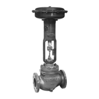
The actuator is mounted on the valve body with the valve body out of the line, following instructions in the actuator manual. The actuator yoke is mounted to the valve body, and mounting cap screws and nuts are tightened to the specified torque. The actuator mounting style and position are determined from provided figures. The actuator is adjusted to bring the disk to the fully closed position at the end of the actuator stroke. Distances between the disk face and seal retainer face at the top and bottom of the valve are measured, and travel stops or turnbuckle are adjusted to ensure these measurements are within 0.8 mm (0.032 inch) of each other. It is crucial to prevent the disk from rotating past the fully closed position to avoid damaging the seal ring.
| Model | 8580 |
|---|---|
| Manufacturer | Fisher |
| Output Current | 4-20 mA |
| Communication Protocol | HART |
| Enclosure Rating | NEMA 4X |
| Operating Temperature | -40 to 85°C |
| Input Voltage | 24 VDC |