D100269X012
Type 128-PQC Control Valves
Contents
Introduction
1. . . . . . . . . . . . . . . . . . . . . . . . . . . . . . .
Scope of Manual 1. . . . . . . . . . . . . . . . . . . . . . . . . . . . .
Description 1. . . . . . . . . . . . . . . . . . . . . . . . . . . . . . . . . .
Specifications 1. . . . . . . . . . . . . . . . . . . . . . . . . . . . . . .
Installation
3. . . . . . . . . . . . . . . . . . . . . . . . . . . . . . . .
Principle of Operation
4. . . . . . . . . . . . . . . . . . .
Maintenance
4. . . . . . . . . . . . . . . . . . . . . . . . . . . . . .
Replacing Packing and Trim 5. . . . . . . . . . . . . . . . . . .
Changing Main Spring Range 6. . . . . . . . . . . . . . . . . .
Reversing Action or Replacing Actuator Parts 6. . . .
Parts Ordering
7. . . . . . . . . . . . . . . . . . . . . . . . . . . .
Parts Kits
7. . . . . . . . . . . . . . . . . . . . . . . . . . . . . . . . .
Parts List
8. . . . . . . . . . . . . . . . . . . . . . . . . . . . . . . . . .
Introduction
Scope of Manual
This manual provides installation, maintenance, and
parts information for the Type 128-PQC control valve.
Instructions and parts lists for Fisher Controls pneu-
matic instrumentation and other equipment used with
this control valve are found in separate manuals.
Only personnel qualified through training or experience
should install, operate, or maintain the Type 128-PQC
control valve. If you have any questions concerning
the instructions in this manual, please contact your
Fisher Controls sales office or sales representative
before proceeding.
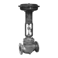
Figure 1. Type 128-PQC Control Valve
W2838-2*/IL
ALTERNATE LOCATION
OF PIPE PLUG FOR USE
AS ANGLE VALVE
LOCATION OF PIPE PLUG
FOR USE AS GLOBE VALVE
Description
The Type 128-PQC control valve provides on-off
dump valve service for such oil production applications
as separators, scrubbers, and treaters, even under
sour gas conditions. It also may be used in general
on-off high-pressure control of a wide variety of liquids
and gases, including those which are sticky or gritty
and erosive. The Type 128-PQC valve is a 1-inch
combination control valve with a pipe plug in the bot-
tom connection for straight-through globe valve flow as
shown in figure 1. However, the pipe plug may be
field-changed to the left-hand end connection as
shown in figure 3 for angle flow.
Specifications
Table 1 lists specifications for the Type 128-PQC con-
trol valve. Some of the specifications for a given con-
trol valve as it originally comes from the factory are
stamped on a nameplate, shown in figure 2, located
on the upper diaphragm casing flange.
Instruction Manual
Form 5086
November 1998
128-PQC