Do you have a question about the Fisher V150 and is the answer not in the manual?
Defines the scope of the instruction manual for V150 and V300 valves.
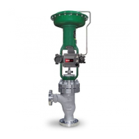
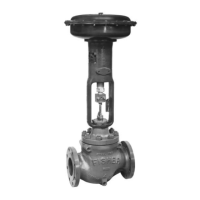
Describes the Design V150 and V300 Vee-Ball® valve features and applications.
Steps for preparing the valve and pipeline before installation, including flange alignment and gasket use.
Instructions for mounting the actuator onto the valve, including pre-shipment adjustments.
Guidance on installing an optional bonding strap for safety in hazardous environments.
Essential safety warnings and cautions prior to performing any maintenance procedures.
Procedures for maintaining valve packing, including stopping leakage and replacement.
Detailed steps for removing and installing ball seals, including disassembly and assembly.
Instructions for disassembling and reassembling valve bearings and the V-notch ball.
Details on standard and optional actuator mounting configurations and flow direction.
Explains index marks for setting actuator lever orientation for different mounting styles.
Procedure to rotate the V-notch ball to its fully open position.
Adjusting the actuator linkage to achieve the correct open position.
Stroking the valve to the closed position and verifying the stroke range.
Guidance on identifying and ordering necessary spare parts using serial and part numbers.
The device described in this manual is the Fisher Design V150 and V300 Vee-Ball® rotary control valve, available in 14, 16, and 20-inch sizes for the V150, and 14 and 16-inch sizes for the V300. These valves are designed for throttling or on-off service, featuring a V-notch ball for precise control. The V150 valve is constructed with raised-face flanges for ANSI Class 150 applications, while the V300 valve is similarly flanged for ANSI Class 300 applications. The valve's splined shaft is designed to connect to various rotary actuators, allowing for versatile control system integration.
The manual emphasizes that only personnel qualified through training or experience should install, operate, and maintain these valves to ensure safety and proper function. It also advises contacting Fisher Controls sales offices or representatives for any questions regarding the instructions.
The Fisher Design V150 and V300 Vee-Ball® rotary control valves are engineered to regulate fluid flow in industrial processes. Their primary function is to provide either precise throttling control, allowing for continuous adjustment of flow rates, or reliable on-off service, where the valve is either fully open or fully closed. The V-notch ball design is central to its control capability, enabling an approximately equal percentage flow characteristic, which means that for a given percentage change in valve travel, there is an equal percentage change in flow. This characteristic is highly desirable in many process control applications for stable and predictable control. The standard flow direction is forward, into the convex sealing face of the V-notch ball. The valve allows for a maximum ball rotation of 90 degrees. When paired with a diaphragm or piston rotary actuator, the valve/actuator action is field-reversible, meaning it can be configured for either push-down-to-close (actuator rod extends to close the valve) or push-down-to-open (actuator rod extends to open the valve). This flexibility allows the valve to be adapted to various control philosophies and safety requirements within a plant.
The installation process for the V150 and V300 valves requires careful attention to detail to ensure proper operation and safety. Before installation, if the valve is to be stored, it's crucial to protect the flange mating surfaces and keep the valve cavity dry and free of foreign material to prevent damage. A three-valve bypass around the control valve assembly is recommended for continuous operation during inspection and maintenance. The valve is typically shipped as part of a complete control valve assembly with the actuator already mounted and factory-adjusted. If the valve and actuator are purchased separately or if the actuator has been removed, specific mounting instructions must be followed. It is essential to ensure that the valve and adjacent pipelines are free of any foreign material that could damage the valve seating surfaces. Mating line flanges must be properly aligned, and standard flat sheet flange gaskets or spiral wound gaskets compatible with the process fluid should be used. The seal protector ring end of the valve requires longer line flange studs than standard, and proper lubrication of studs with Never-Seez Pure Nickel Special or an equivalent is advised. All nuts should be tightened in a criss-cross sequence to ensure proper loading of flange gaskets. For hazardous applications, an optional bonding strap assembly should be attached to the valve drive shaft and connected to the valve body to prevent static electricity discharge, which could lead to explosions if the process fluid or atmosphere is flammable. Pressure lines to the actuator should be connected as indicated in the actuator instruction manual, and if an auxiliary manual actuator is used with a power actuator, a bypass valve should be installed for manual operation. The manual also highlights that the valve drive shaft is not necessarily grounded when installed in a pipeline, underscoring the importance of electrical bonding in hazardous areas.
Maintenance of the V150 and V300 valves is critical for ensuring their longevity and reliable performance. Valve parts are subject to normal wear and must be inspected and replaced as necessary, with frequency depending on service conditions. Only replacement parts manufactured or furnished by Fisher Controls should be used. A significant warning is issued regarding the V-notch ball's cutting motion during closing, advising to keep hands, tools, and other objects away from it to prevent personal injury. Before any maintenance, it's imperative to disconnect operating lines providing air pressure, electric power, or control signals to the actuator and ensure it cannot suddenly open or close the valve. Process pressure must be completely shut off, and the valve isolated from the process, with pressure relieved and media drained from both sides. Power actuator loading pressure should be vented, and lock-out procedures implemented to ensure these safety measures remain in effect.
Packing maintenance is a key aspect. For PTFE V-ring packing, leakage around the packing follower and flange can often be stopped by tightening the packing follower nuts. If tightening doesn't work, the drive shaft may be worn or nicked, or the packing box wall may be scratched or corroded, necessitating packing replacement. When replacing packing, it's not recommended to remove the actuator while the valve is in the pipeline, as valve/actuator adjustments require the valve to be out of the pipeline. Disassembly involves isolating the valve, removing it from the pipeline, and placing it on a protected surface. The actuator cover is removed, noting its orientation and the lever's orientation relative to the valve drive shaft. A warning is given that the V-notch ball/shaft assembly may suddenly rotate after actuator removal, emphasizing careful rotation to a stable position. When removing the actuator, a wheel puller should be used, avoiding hammers or excessive force to prevent damage to the V-notch ball, seal, and valve. For ENVIRO-SEAL packing systems, specific instruction manuals should be consulted. Packing parts are removed using a formed wire hook, taking care not to scratch the drive shaft or packing box wall. Assembly involves installing new packing parts in the correct sequence, securing them with the packing follower nuts, and reconnecting the actuator and lever according to noted orientations and index marks.
Ball seal replacement is performed if the control valve isn't shutting off properly or if seal inspection is needed. This procedure also requires removing the actuator/valve assembly from the pipeline. The actuator can remain mounted during ball seal inspection and replacement. If the V-notch ball, drive shaft, or bearings need replacement, the ball seal procedure is followed by the V-notch Ball and Bearing Maintenance procedures. During disassembly, the seal protector ring, seal, and other parts must be handled carefully to prevent damage, and a new gasket is required whenever the seal protector ring is removed. For flow ring constructions, the seal and other seal parts are disregarded. The retainer screws are removed, and the seal protector ring and gasket are carefully taken out. For composition seals, the seal is removed from the valve body. For HD metal seals, the metal seal is pushed out of the seal protector ring, and the radial seal is removed. All parts are inspected, cleaned, or replaced as necessary. Lifting bolt holes are provided in the seal retainer or flow ring to assist in removal.
Bearing and V-notch ball maintenance procedures are performed after the ball seal and valve packing are loosened. This involves removing the actuator. An "eye" bolt can be installed into the V-notch ball cavity to assist in lifting and controlling its rotation. The valve is placed on a protected working surface with the seal side down. Pins are driven out of the drive shaft and follower shaft, breaking any tack welds. The valve is then carefully lifted, and the bottom flange and gasket are removed. The follower shaft is pushed into the V-notch ball, and the drive shaft is pulled out. Bearings are removed, either by hand for PEEK bearings or with a press and ram for metal bearings. All parts are thoroughly cleaned, and replacement parts obtained. Assembly involves installing bearings, ensuring correct positioning, and then carefully installing the V-notch ball, drive shaft, and follower shafts. Special care is taken to align the splined ear of the V-notch ball with the packing box side of the valve body and to support the ball to prevent damage during insertion. The bottom flange, gasket, and nuts are then installed and hand-tightened. Pins are inserted and tack welded to the ball ears. The bottom flange nuts are tightened to specified torque values. Finally, the ball seal and seal protector ring are installed, and the actuator is mounted, ensuring the V-notch ball closes in the downward direction. Actuator travel must be adjusted before installing the valve in the pipeline. The actuator can be mounted in various right-hand or left-hand positions, though changing between these may require a different valve drive shaft and V-notch ball. Determining the open position involves rotating the V-notch ball to its open position and adjusting the actuator linkage, then stroking the valve to the closed position, ensuring it doesn't stroke more than 90 degrees. For parts ordering, the serial number from the nameplate and the complete 11-character part number from the parts list are essential.
| Shutoff Classification | Class IV |
|---|---|
| Actuation | Pneumatic |
| Materials | Carbon Steel, Stainless Steel |
| Operating Temperature | -50°F to 450°F (-46°C to 232°C) |
| Application | General Purpose |
| Input Voltage | Not applicable (valve only) |
| Communication Protocol | Not applicable (valve only) |
| Enclosure Rating | Not applicable (valve only) |
| Mounting | Flanged |
| Output Current | Not applicable (valve only) |