Instruction Manual
D103042X012
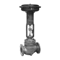
D4 Valve
July 2015
4
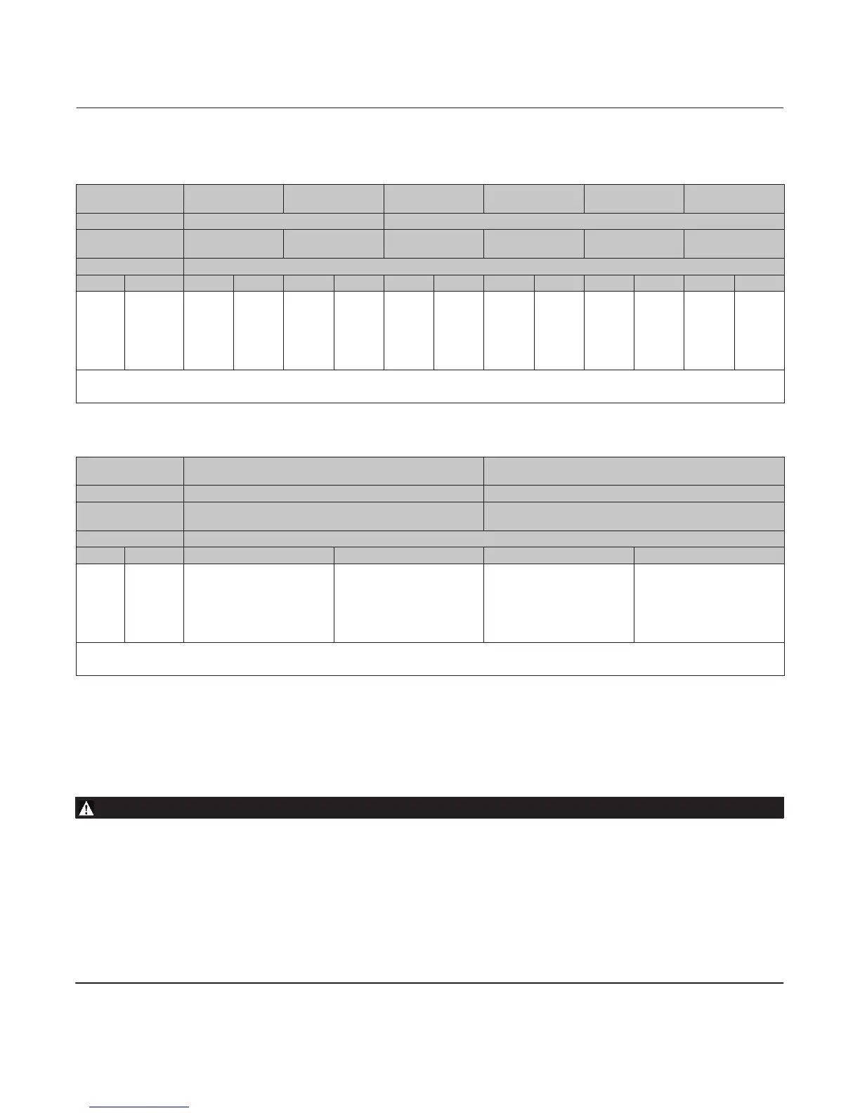
Table 6. Maximum Shutoff Pressure Drops
(1)
for Fisher D4 Control Valves (Spring‐to‐Open)
When Used with Typical Control Instrumentation
(2)
INPUT SIGNAL TO
ACTUATOR
0 to 1.2 Bar
(0 to 18 Psig)
0 to 1.4 Bar
(0 to 20 Psig)
0 to 2.0 Bar
(0 to 30 Psig)
0 to 2.3 Bar
(0 to 33 Psig)
0 to 2.4 Bar
(0 to 35 Psig)
0 to 3.4 Bar
(0 to 50 Psig)
SPRING Light Rate Heavy Rate
INITIAL SPRING
SETTING
0.23 Bar
(3.4 Psig)
0.23 Bar
(3.4 Psig)
0.28 Bar
(4.0 Psig)
0.28 Bar
(4.0 Psig)
0.28 Bar
(4.0 Psig)
0.28 Bar
(4.0 Psig)
PORT DIAMETER Maximum Pressure Drop
mm Inches Bar Psi Bar Psi Bar Psi Bar Psi Bar Psi Bar Psi
6.4
9.5
12.7
19.1
25.4
31.8
0.25
0.375
0.5
0.75
1
1.25
293
(3)
293
(3)
187
78
41
24
4250
(3)
4250
(3)
2715
1135
600
355
293
(3)
293
(3)
233
99
53
32
4250
(3)
4250
(3)
3380
1430
765
465
293
293
293
147
80
49
4250
4250
4250
2130
1160
715
293
293
293
178
97
60
4250
4250
4250
2575
1410
875
293
293
293
198
109
68
4250
4250
4250
2875
1575
985
293
293
293
293
195
123
4250
4250
4250
4250
2830
1785
1. The pressure or temperature limits in the referenced tables and any applicable ASME code limitations should not be exceeded.
2. For example, use the column marked 0‐1.4 bar (0‐20 psig) for a 0.21‐1.0 bar (3‐15 psig) pneumatic controller with 1.4 bar (20 psig) supply pressure.
3. For applications with downstream pressure in excess of 190 bar (2760 psig), use 190 bar (2760 psig) for Maximum Shutoff Pressure.
Table 7. Maximum Shutoff Pressure Drops
(1)
for Fisher D4 Control Valves (Spring‐to‐Open)
When Used with Instrumentation with Restricted Output Range
(2)
INPUT SIGNAL TO
ACTUATOR
0.4 to 2.0 Bar
(6 to 30 Psig)
0.14 to 2.3 Bar
(2 to 33 Psig)
SPRING Heavy Rate Heavy Rate
INITIAL SPRING
SETTING
0.69 Bar
(10.0 Psig)
0.42 Bar
(6.1 Psig)
PORT DIAMETER Maximum Pressure Drop
mm Inches Bar Psi Bar Psi
6.4
9.5
12.7
19.1
25.4
31.8
0.25
0.375
0.5
0.75
1
1.25
293
(3)
293
(3)
196
82
43
26
4250
(3)
4250
(3)
2845
1195
630
380
293
293
293
156
85
52
4250
4250
4250
2265
1235
765
1. The pressure or temperature limits in the referenced tables and any applicable ASME code limitations should not be exceeded.
2. For example, an Electro‐Pneumatic Transducer calibrated for 0.4‐2.0 bar (6‐30 psig) output pressure.
3. For applications with downstream pressure in excess of 202 bar (2925 psig), use 202 bar (2925 psig) for Maximum Shutoff Pressure.
Installation
WARNING
Always wear protective gloves, clothing, and eyewear when performing any installation operations to avoid personal
injury.
To avoid personal injury or property damage caused by bursting of pressure‐retaining parts or by uncontrolled process
fluid, be certain the service conditions do not exceed the limits shown on the valve nameplate and in tables 1, 4, 5, 6, and 7.
Use pressure‐relieving devices required by government or accepted industry codes and good engineering practices.
Check with your process or safety engineer for any additional measures that must be taken to protect against process
media.
If installing into an existing application, also refer to the WARNING at the beginning of the Maintenance section in this
instruction manual.