EasyManua.ls Logo

Fisher 377 User Manual

Fisher 377
20 pages
To Next Page IconTo Next Page
Page #1 background imageLoading...
Page #1 background image
www.Fisher.com
Fisher
r
377 Trip Valve
Contents
Introduction 1.................................
Scope of Manual 1.............................
Description 1.................................
Specifications 3...............................
Educational Services 3.........................
Installation 4..................................
Supply Pressure Requirements 5.................
Operating Information 8.........................
Calibration 8.................................
Principle of Operation 10........................
377D Trip Valve 10............................
377L Trip Valve 11.............................
377U Trip Valve 12............................
Maintenance 12................................
Periodic Operational Check 12...................
Trip Valve Part Replacement Procedures 13........
Replacing Diaphragms and Valve Plug Parts 13.....
Replacing Stem/Plug Assembly Parts 14...........
Parts Ordering 15...............................
Parts Kits 15...................................
Parts List 15...................................
Figure 1. Fisher 377 Trip Valve Mounted on Size 130
585C Actuator
W8435‐1
Introduction
Scope of Manual
This instruction manual provides installation, operation, maintenance, and parts information for the Fisher 377 trip
valve. Refer to separate instruction manuals for information regarding the control valve, actuator, and accessories.
Do not install, operate, or maintain a 377 trip valve without being fully trained and qualified in valve, actuator and
accessory installation, operation, and maintenance. To avoid personal injury or property damage, it is important to
carefully read, understand, and follow all of the contents of this manual, including all safety cautions and warnings. If
you have any questions regarding these instructions contact your Emerson Process Management sales office before
proceeding.
Description
377 pressure‐sensing trip valves, shown in figures 1, 2, and 3, are for control applications where a specific
valve/actuator action is required when supply pressure falls below a specific point. When supply pressure falls below
the trip point, the trip valve cause the actuator to fail up, lock in the last position, or fail down. When the supply
pressure rises above the trip point, the 377 trip valve automatically resets, allowing the system to return to normal
operation. The trip valve can be top‐mounted on a manifold, yoke‐mounted, or bracket‐mounted to match the
application requirements. 377 trip valves are used with all types of piston actuators.
Instruction Manual
D200319X012
377 Trip Valve
August 2012
Question and Answer IconNeed help?

Do you have a question about the Fisher 377 and is the answer not in the manual?

Fisher 377 Specifications

General IconGeneral
Power Supply24 VDC
Communication ProtocolHART
Input Signal4-20 mA
Operating Temperature-40 to +180°F (-40 to +82°C)
Ambient Temperature Range-40 to +180°F (-40 to +82°C)
Enclosure RatingNEMA 4X

Summary

Introduction to Fisher 377 Trip Valve

Scope of Manual

Provides installation, operation, maintenance, and parts information for the Fisher 377 trip valve.

Description of 377 Trip Valve

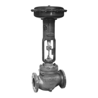
Explains 377 pressure-sensing trip valves and their applications where specific valve/actuator action is required.

Specifications for 377 Trip Valves

General Specifications

Details technical specifications for 377 trip valves, including configurations, pressure, temperature, and flow coefficients.

Educational Services Information

Provides contact information for available training courses for 377 trip valves and other products.

Installation Procedures and Warnings

Installation Safety Warning

Safety warnings regarding personal injury from sudden release of process pressure during installation.

Installation Caution

Caution regarding leak testing and the integrity of control system accessories with trip valves.

Supply Pressure Requirements

Supply Pressure Safety Warning

Safety warning about potential injury if instrument air supply is not clean, dry, and oil-free.

Critical Warnings and Cautions

Hazardous Gas Warning

Warning about potential injury from flammable/hazardous gas and the need for ventilation.

Pipe Compound Caution

Caution regarding excessive pipe compound and its effect on trip valve operation.

Operating Information and Calibration

Calibration Procedure

Procedure for calibrating the trip valve, including safety precautions.

Calibration Safety Warning

Safety warning for taking the trip valve out of service during calibration.

Principle of Operation

377D Trip Valve Operation

Explains the fail-down mode operation of the 377D trip valve.

377L Trip Valve Operation

377U Trip Valve Operation

Maintenance and Operational Checks

Maintenance Safety Warning

Safety warnings for performing maintenance operations on the trip valve.

Periodic Operational Check Warning

Safety warning for taking the trip valve out of service for periodic checks.

Trip Valve Part Replacement

Part Replacement Safety Warning

Warning for isolating valve and releasing pressure before part replacement.

Diaphragm and Valve Plug Caution

Caution to prevent damage to the upper diaphragm during replacement.

Replacing Stem/Plug Assembly Parts

Parts Information

Parts Ordering Guidance

Information on ordering replacement parts, referencing serial numbers.

Available Parts Kits

Details on available repair kits including common components.

Common Parts List

Lists common parts for trip valve construction with key numbers and materials.

Fittings for Trip Valve Installation

Related product manuals