Instruction Manual
D103042X012
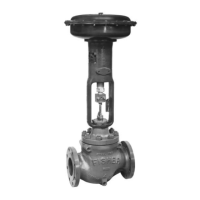
D4 Valve
July 2015
3
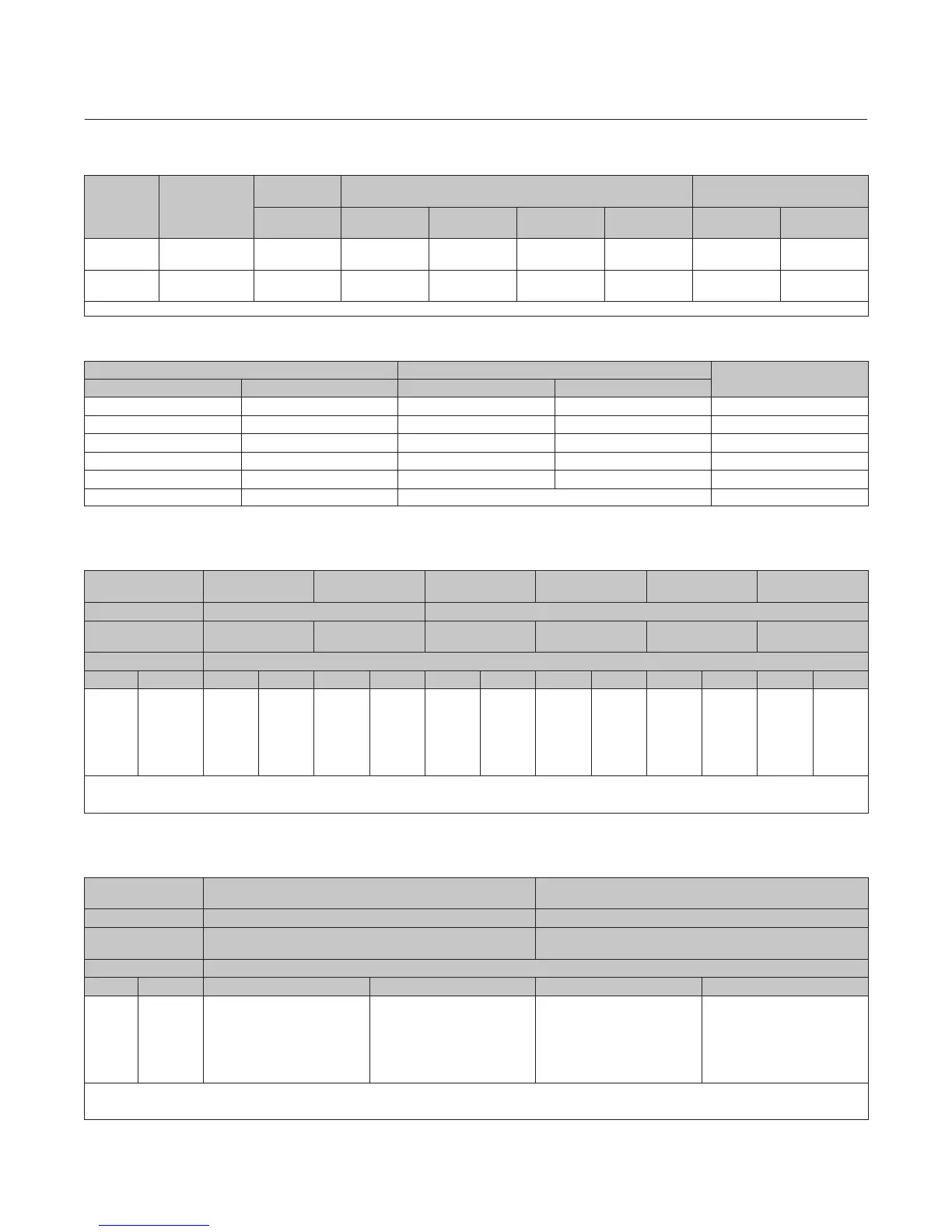
Table 2. Valve Sizes and Connection Styles
VALVE
SIZE,
NPS
PORT
DIAMETER,
(INCHES)
SCREWED RAISED FACE (RF) FLANGED
RING TYPE JOINT
(RTJ) FLANGED
4250 psi CL150 CL300 CL600
CL900 and
CL1500
CL600
CL900 and
CL1500
1
0.25, 0.375,
0.5, 0.75
X X X X X X X
2
0.25, 0.375, 0.5
0.75, 1, 1.25
X X X X X X X
X = Available construction.
Table 3. D4 Environmental Limits for NACE MR0175/ISO 15156 with Sour Trim
MAXIMUM TEMPERATURE MAXIMUM H
2
S PARTIAL PRESSURE
COMPATIBLE WITH
ELEMENTAL SULFUR?
_C _F MPa psia
232 450 0.2 30 No
204 400 1.4 200 No
199 390 2.3 330 No
191 375 2.5 360 No
149 300 2.8 400 No
135 275 No Limit Yes
Table 4. Maximum Shutoff Pressure Drops
(1)
for Fisher D4 Control Valves (Spring‐to‐Close)
When Used with Typical Control Instrumentation
(2)
INPUT SIGNAL TO
ACTUATOR
0 to 1.2 Bar
(0 to 18 Psig)
0 to 1.4 Bar
(0 to 20 Psig)
0 to 2.0 Bar
(0 to 30 Psig)
0 to 2.3 Bar
(0 to 33 Psig)
0 to 2.4 Bar
(0 to 35 Psig)
0 to 3.4 Bar
(0 to 50 Psig)
SPRING Light Rate Heavy Rate
INITIAL SPRING
SETTING
0.77 Bar
(11.2 Psig)
0.77 Bar
(11.2 Psig)
0.85 Bar
(12.4 Psig)
1.05 Bar
(15.3 Psig)
1.18 Bar
(17.1 Psig)
1.18 Bar
(17.1 Psig)
PORT DIAMETER Maximum Pressure Drop
mm Inches Bar Psi Bar Psi Bar Psi Bar Psi Bar Psi Bar Psi
6.4
9.5
12.7
19.1
25.4
31.8
0.25
0.375
0.5
0.75
1
1.25
293
(3)
293
(3)
191
80
42
25
4250
(3)
4250
(3)
2765
1160
610
365
293
(3)
293
(3)
191
80
42
25
4250
(3)
4250
(3)
2765
1160
610
365
293
293
219
92
49
30
4250
4250
3180
1340
715
430
293
293
288
123
67
41
4250
4250
4180
1785
965
590
293
293
293
143
78
48
4250
4250
4250
2080
1130
700
293
293
293
143
78
48
4250
4250
4250
2080
1130
700
1. The pressure or temperature limits in the referenced tables and any applicable ASME code limitations should not be exceeded.
2. For example, use the column marked 0‐1.4 bar (0‐20 psig) for a 0.21‐1.0 bar (3‐15 psig) pneumatic controller with 1.4 bar (20 psig) supply pressure.
3. For applications with downstream pressure in excess of 196 bar (2845 psig), use 196 bar (2845 psig) for Maximum Shutoff Pressure.
Table 5. Maximum Shutoff Pressure Drops
(1)
for Fisher D4 Control Valves (Spring‐to‐Close)
When Used with Instrumentation with Restricted Output Range
(2)
INPUT SIGNAL TO
ACTUATOR
0.4 to 2.0 Bar
(6 to 30 Psig)
0.14 to 2.3 Bar
(2 to 33 Psig)
SPRING Heavy Rate Heavy Rate
INITIAL SPRING
SETTING
0.97 Bar
(14.0 Psig)
1.17 Bar
(17.0 Psig)
PORT DIAMETER Maximum Pressure Drop
mm Inches Bar Psi Bar Psi
6.4
9.5
12.7
19.1
25.4
31.8
0.25
0.375
0.5
0.75
1
1.25
293
(3)
210
(3)
113
45
23
13
4250
(3)
3045
(3)
1635
655
330
185
293
293
282
120
65
39
4250
4250
4095
1750
945
580
1. The pressure or temperature limits in the referenced tables and any applicable ASME code limitations should not be exceeded.
2. For example, an Electro‐Pneumatic Transducer calibrated for 0.4‐2.0 bar (6‐30 psig) output pressure.
3. For applications with downstream pressure in excess of 118 bar (1715 psig), use 118 bar (1715 psig) for Maximum Shutoff Pressure.