between the rst and second
Type
EZR regulators.
Connect the “A” port of upstream
Type
PRX-125 pilot
downstream of both regulators.
The pilot supply pressure connection for the
downstream Type EZR regulator must be directly
upstream of the Type EZR using intermediate pressure
and connected to the “S” port of the downstream
Type PRX-120. Install a Type 252 pilot supply lter
upstream of the pilot, if needed, to keep the supply
source from clogging the restrictor in the pilot. Inspect
and clean this lter regularly to make sure it has not
been plugged. Connect the loading port (Port L) of the
downstream Type PRX-120 pilot to the bonnet of the
downstream Type EZR regulator. Connect the “A” and
“B” ports of the downstream Type PRX-120 pilot to
downstream pressure.
Startup and Adjustment
Note
Table 10 shows the maximum inlet
and differential pressures for specic
constructions. Use pressure gauges to
monitor inlet pressure, outlet pressure
and any intermediate pressure
during startup.
CAUTION
To prevent damage to the Type PRX pilot
during startup, the sense and bleed lines
of the Type PRX should be located on the
same side of the downstream block valve.
Keep sense and bleed lines separate.
Startup for Both Single-Regulator and
Monitoring Installations
1. Make sure all block and vent valves are closed.
2. Back out the pilot adjusting screw(s).
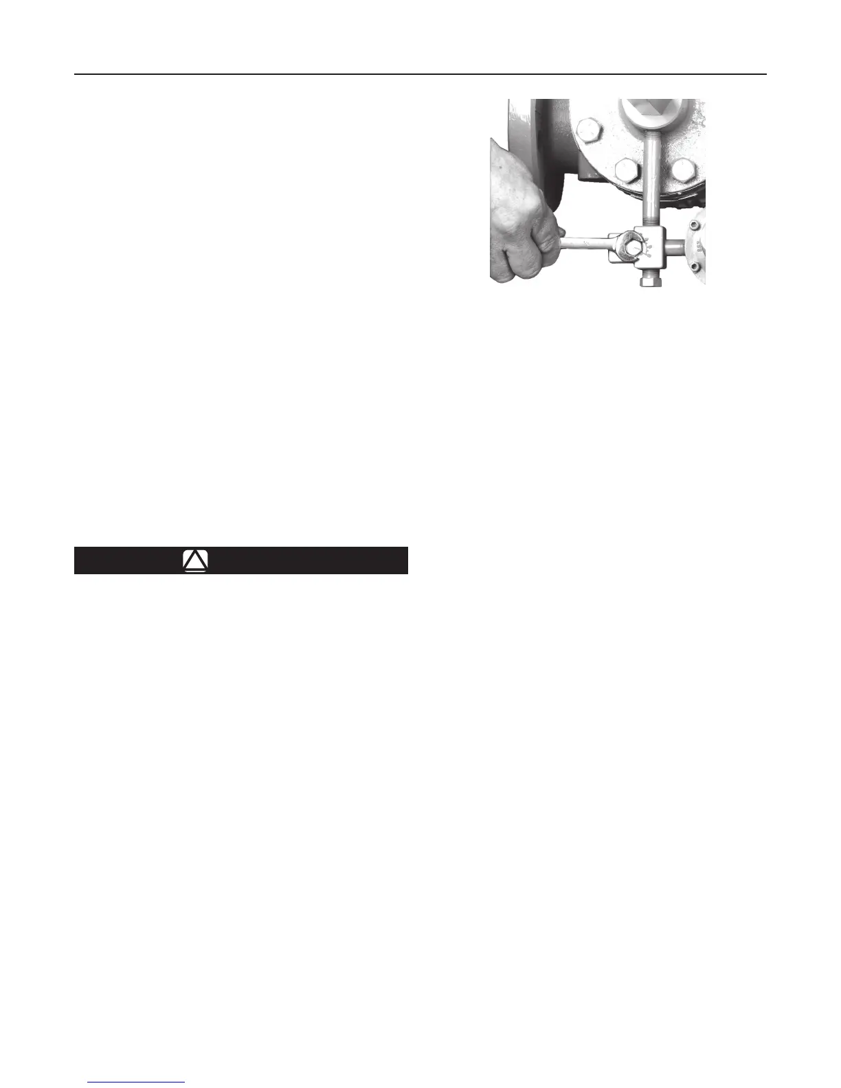
3. For easy initial startup, set the restrictor to the “8”
position. For future startups, the restrictor can be
left in the desired run position.
4. SLOWLY OPEN the valves in the following order:
a. Pilot supply and control line valve(s), if used
b. Inlet block valve
c. Outlet block valve
5. For a 161 Series pilot with Type 112 restrictor,
turn the restrictor(s) to position “2” or to the
desired run position. For a PRX Series pilot, turn
the restrictor screw 1 turn counterclockwise from
fully seated (turn restrictor fully clockwise then
1 turn counterclockwise) and the damper screw
fully counterclockwise.
6. For a single regulator, set the pilot to the desired
outlet (control) pressure according to the pilot
adjustment procedure.
For a wide-open downstream monitor
installation, adjust the upstream working pilot until
intermediate pressure is higher than the desired
setpoint of the monitor pilot. Adjust the downstream
monitoring pilot to the desired monitoring takeover
pressure. Reduce the upstream pilot to the normal
outlet pressure setting.
For a wide-open upstream monitor installation,
adjust the downstream working pilot to a setpoint
higher than the setpoint of the monitor pilot.
Adjust the upstream monitoring pilot to the desired
monitor takeover pressure. Reduce the downstream
pilot setting to normal outlet pressure setting.
For a working monitor installation, turn out the
adjusting screw of the downstream pilot, removing
spring tension. Adjust the upstream working pilot
to the desired intermediate pressure setting. Turn
out the adjusting screw of the upstream monitor
pilot, removing spring tension. Turn in the adjusting
screw of the downstream pilot. Adjust the upstream
monitor pilot to the desired setpoint taking into
account the guidelines shown in Table 9. Establish
nal desired downstream pressure by adjusting the
downstream pilot.
Pilot Adjustment
For 161 Series pilots, remove the pilot closing cap
(key 16, Figure 19 or key 22, Figure 20) and, on
161EB Series only, loosen the locknut (key 12,
Figure 19). Turn the adjusting screw (key 11,
Figure 19 or key 35, Figure 20) into the spring case
(key 2, Figure 19 or key 3, Figure 20) to increase the
downstream pressure. Turn the adjusting screw out of
the spring case to decrease the downstream pressure.
Figure 6. Restrictor Adjustment
W4559_1
11
Type EZR

 Loading...


