Working Monitor Installations
On working monitor installations, the working monitor
regulator is always upstream and acts as a rst-stage
regulator through the working pilot during normal
operation. This arrangement allows the working
monitor’s performance to be observed at all times.
Then, should the second-stage regulator fail open,
the working monitor regulator assumes the entire
pressure reduction function of the system through the
monitoring pilot.
Use the following procedure when installing a working
monitor system.
1. Follow the procedures in the All Installations
section and then continue with step 2 of
this section.
2. Pilot supply pressure for the downstream
Type EZR regulator must be made directly
upstream of the Type EZR using
intermediate pressure.
3. Table 9 gives the spread between normal
distribution pressure and the minimum pressure at
which the monitor pilot can be set to take over if
the working regulator fails open.
4. Table 4 shows the minimum differential pressure
requirements across an individual regulator.
Because this application uses a rst-stage
and second-stage pressure reduction, add the
minimum differential pressure for each regulator
together to establish the required pressure drop
across the station. Do not exceed maximum pilot
ratings given in Table 3.
For Type PRX Working Monitor
As shown in Figure 5, run a supply pressure line
(use 3/8 NPT outer diameter tubing or larger) from the
upstream pipeline to the inlet (Port S) of the upstream
Type PRX-120 pilot. Install a Type 252 pilot supply
lter upstream of the pilot, if needed, to keep the
supply source from clogging the restrictor in the pilot.
Inspect and clean this lter regularly to make sure it
has not been plugged.
Connect the loading port (Port L) of the upstream
Type PRX-120 pilot to the bonnet of the upstream
Type EZR regulator. Connect the “B” port of the upstream
Type PRX-120 pilot to the “S” port of the upstream
Type PRX-125 pilot. Connect the “A” port (located on the
underside of the pilot) of the upstream Type PRX-120 pilot
to the intermediate pressure between the rst and second
Type EZR regulators as shown in Figure 5.
The “L” port of the upstream
Type
PRX-125 pilot is
plugged. Connect the “B” port of upstream
Type
PRX-125 pilot to the intermediate pressure
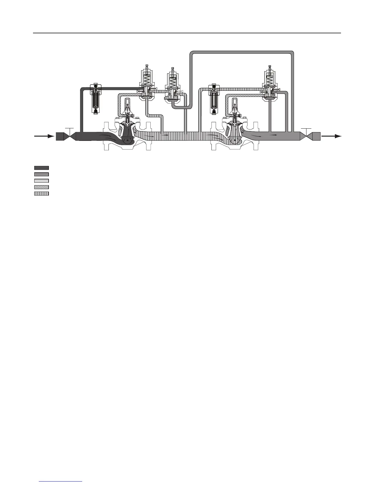
Figure 5. Type EZR-PRX-PRX Working Monitor Schematic
INLET PRESSURE
OUTLET PRESSURE
ATMOSPHERIC PRESSURE
LOADING PRESSURE
INTERMEDIATE PRESSURE
TYPE PRX:
S- SUPPLY PORT
B- BLEED PORT
L- LOADING PORT
A - SENSING PORT
INLET
TYPE PRX/120
PILOT
TYPE PRX/125
PILOT
S
S
FILTER
FILTER
L
A
A
B
B
INTERMEDIATE
OUTLET
TYPE PRX/120
PILOT
S
L
A
B
M1001_05/2016
10
Type EZR

 Loading...


