6. As shown in Figure 3, run a supply pressure line
from the upstream pipeline to the restrictor inlet
(use 3/8 NPT outer diameter tubing or larger).
Install a Type 252 pilot supply lter upstream of the
restrictor, if needed, to keep the supply source
from clogging the restrictor or pilot. Inspect and
clean this lter regularly to make sure it has not
been plugged.
7. Install a downstream pressure control line (as
shown in the appropriate view of Figure 3) to the
pilot control line connection. Connect the other
end of the control line at a minimum of 8 to 10 pipe
diameters downstream of the regulator in a straight
run of pipe. Do not place a control line connection in
a turbulent area, such as in or directly downstream
of a swage or elbow. Signicant restrictions in the
control line can prevent proper pressure registration.
When using a hand valve, it should be a full ow
valve, such as a full port ball valve. With a
Type 161EBM or 161AYM pilot or a PRX Series
pilot, run a downstream exhaust bleed line to the
downstream bleed line connection in the pilot
body assembly.
8. Good piping practices usually require swaging up
to larger downstream piping to obtain reasonable
downstream uid velocity.
Wide-Open Monitor Installations
1. Follow the procedures in the All Installations section
and then continue with step 2 of this section.
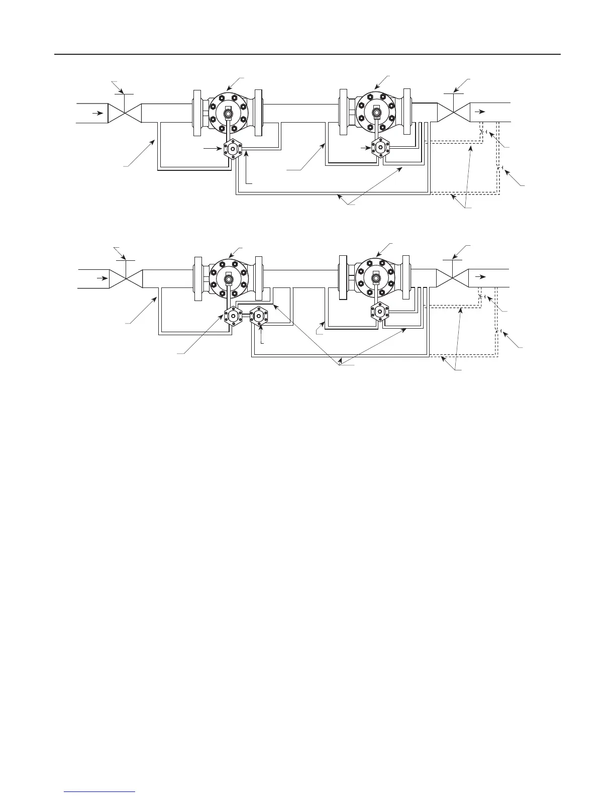
2. Pilot supply for the downstream monitoring regulator
must be obtained between the two regulators as
s
hown in Figure 4. For sizing purposes, add the
minimum differential pressure for each regulator
together to establish the required pressure drop
across the station.
3. In a wide-open Type EZR monitoring system, system
lockup will be that of the worker regulator on both an
upstream monitor when the upstream pilot exhaust is
piped to the intermediate pressure and a downstream
monitor with upstream pilot exhaust piped to either
intermediate pressure or outlet pressure. With these
congurations, the diaphragm of the monitor regulator
will change position with every load change. On an
upstream monitor with the upstream pilot exhaust
piped to downstream, lockup will occur at the
monitor’s setpoint and the diaphragm of the monitor
regulator will be fully open during normal conditions.
BLOCK VALVE
UPSTREAM REGULATOR
DOWNSTREAM
REGULATOR
BLOCK VALVE
OUTLET
INLET
SUPPLY
PRESSURE LINE
PILOT
EXHAUST
TYPE PRX
PILOT
SUPPLY
PRESSURE
LINE
TYPE PRX
PILOT
CONTROL LINE
ALTERNATE
CONTROL LINE
HAND
VALVE
HAND
VALVE
Figure 4. Typical Type EZR Monitoring System Installation Schematics (continued)
TYPE PRX WORKING MONITOR SYSTEM INSTALLATION
CONTROL LINE
TYPE PRX WIDE-OPEN MONITORING SYSTEM INSTALLATION WITH PILOT EXHAUST TO INTERMEDIATE PRESSURE
BLOCK VALVE
MONITOR REGULATOR
WORKING
REGULATOR
BLOCK VALVE
OUTLET
INLET
SUPPLY
PRESSURE LINE
TYPE PRX-120
WORKING PILOT
TYPE PRX-125
MONITOR PILOT
SUPPLY
PRESSURE
LINE
ALTERNATE
CONTROL LINE
HAND
VALVE
HAND
VALVE
L
(1)
L
A
A
S
S
B
B
(1) PLUGGED
9
Type EZR

 Loading...


